
MIL-STD-461 Power Supplies
Selecting power supplies that meet aircraft, shipboard, and ground electromagnetic interference requirements

A switching power supply is one of the largest sources of electromagnetic interference in a piece of military equipment. It draws pulsed current from the input, switches high voltages at high frequency, and drives currents through cables that behave like antennas. If EMI is treated as a late-stage test rather than a design requirement, the power supply is usually the first thing to fail it.
MIL-STD-461 defines the electromagnetic interference emissions and susceptibility requirements for equipment and subsystems used by the Department of Defense. It sets the test methods, the frequency ranges, and the limit levels the equipment must meet so that many systems can operate together on the same platform without interfering with each other or being disrupted by their environment.
The current revision is MIL-STD-461G (2015). It is an equipment-level standard: the box you deliver must control what it emits onto its power and signal leads and into the surrounding space, and it must keep operating when subjected to the specified conducted and radiated disturbances. This page explains which MIL-STD-461 requirements a power supply actually drives and helps you match the requirement to the right Abbott architecture.
What MIL-STD-461 Asks of Your Power Supply
MIL-STD-461 is organized around a set of emissions and susceptibility requirements, each with a two-letter and number designation (for example CE102 or CS114). For power conversion hardware, the ones that matter break down into a few design areas:
| Design area | Why it matters |
|---|---|
| Conducted emissions | The pulsed input current and switching noise a supply puts back onto its power leads (CE101, CE102) are controlled by the input EMI filter, the switching topology, and grounding. This is where bare converter modules most often fail. |
| Radiated emissions | Switching edges, high-current loops, and cabling radiate electric and magnetic fields (RE101, RE102). Enclosure shielding, bonding, internal layout, and filtered feedthroughs control them. |
| Conducted susceptibility | The supply must keep regulating while ripple, RF, and transients are injected onto its power and signal leads (CS101, CS114, CS115, CS116). Input filtering, control-loop margin, and holdup all contribute. |
| Transients, lightning, and ESD | Revision G adds lightning-induced transients (CS117) and personnel-borne electrostatic discharge (CS118). Input transient suppression and enclosure bonding determine survival. |
| Radiated susceptibility | The supply must operate through external RF and magnetic fields (RS101, RS103) at the specified field strength without loss of regulation or false shutdown. |
| Filtering and bonding | Meeting the limits depends on a designed-in EMI filter, low-impedance chassis bonding, controlled shield termination, and a clean grounding architecture, not on adding a filter at the end. |
| Evidence and configuration control | The configuration tested must match the configuration delivered. Changes to the input filter, harnessing, connectors, grounding, or enclosure bonding can change the EMI result and invalidate prior evidence. |
The practical takeaway: EMI performance is set by the power supply architecture and its installation, so it has to be engineered in from the start, not filtered out at qualification.
The MIL-STD-461 Tests That Apply to Power Conversion
MIL-STD-461G defines roughly twenty emissions and susceptibility methods. Many target antenna ports on transmitters and receivers and do not apply to a power supply. The methods below are the ones that typically drive power conversion design. Confirm the exact set and limit levels against the requirements your equipment specification invokes.
| Method | What it verifies | Frequency range |
|---|---|---|
| CE101 | Conducted emissions on power leads at audio frequencies: the low-frequency ripple current the supply draws. Common on Navy and submarine equipment. | 30 Hz to 10 kHz |
| CE102 | Conducted emissions on power leads at radio frequencies: the primary conducted-emissions limit for a power supply, controlled by the input EMI filter. | 10 kHz to 10 MHz |
| RE101 | Radiated magnetic field emissions from transformers, inductors, and high-current loops. Emphasized for shipboard and submarine installations. | 30 Hz to 100 kHz |
| RE102 | Radiated electric field emissions: broadband noise from switching edges and cabling, controlled by shielding, bonding, and filtering. | 10 kHz to 18 GHz |
| CS101 | Conducted susceptibility on power leads: injected ripple the supply must operate through without loss of regulation. | 30 Hz to 150 kHz |
| CS114 | Bulk cable injection: RF injected onto interconnecting cables and power leads. The supply must keep regulating. | 10 kHz to 200 MHz |
| CS115 | Bulk cable injection, impulse excitation: fast impulse currents on cables. Applies to aircraft, ground, and space equipment. | Impulse |
| CS116 | Damped sinusoidal transients on cables and power leads: the ringing transients that follow switching and lightning events. | 10 kHz to 100 MHz |
| CS117 | Lightning-induced transients on cables and power leads. Added in revision G for aircraft and exposed equipment. | Transient |
| CS118 | Personnel-borne electrostatic discharge to the equipment. Added in revision G. | ESD |
| RS101 | Radiated susceptibility to magnetic fields. Emphasized for Navy surface ship and submarine equipment. | 30 Hz to 100 kHz |
| RS103 | Radiated susceptibility to electric fields: the external RF environment the supply must operate through at the specified field strength. | 2 MHz to 40 GHz |
Selection note: MIL-STD-461 does not apply one fixed set of limits to every product. The applicable methods and the limit levels are set by the equipment specification and the platform, using the requirements matrix in MIL-STD-461G. Confirm the revision, the invoked methods, and the platform before you assume a limit.
How the Requirements Are Tailored by Platform
The same power supply faces different MIL-STD-461 requirements depending on where it is installed. The requirements matrix in revision G maps each method to the platform and installation. The general emphasis for power equipment:
| Platform group | Typical emphasis for a power supply |
|---|---|
| Aircraft (Army, Navy, Air Force) | CE102 and RE102 emissions; CS114, CS115, and CS116 cable susceptibility; RS103 radiated susceptibility; CS117 lightning where the installation is exposed. |
| Ground | CE102 and RE102 emissions; CS114, CS115, and CS116 cable susceptibility; RS103 radiated susceptibility. |
| Navy surface ship | Adds low-frequency CE101 conducted emissions, RE101 magnetic emissions, RS101 magnetic susceptibility, and structure-current and transient methods to the aircraft and ground set. |
| Submarine | The most stringent low-frequency magnetic requirements (RE101, RS101, CE101), reflecting the sensitivity of the shipboard environment. |
| Space and launch vehicle | CE102 and RE102 emissions; CS114, CS115, and CS116 cable susceptibility; RS103 and transient methods. |
Why a complete unit, not just a module: a bare DC-DC or AC-DC module has no input EMI filter, no shielded enclosure, and no bonding scheme, so on its own it will not meet CE102, RE102, or the cable-injection susceptibility limits. A complete Abbott power supply integrates the EMI filter, the shielding, the transient suppression, and the chassis bonding needed to meet the emissions and susceptibility requirements as a delivered unit. That is the difference between a component that regulates voltage and a subsystem that passes MIL-STD-461. Confirm the revision (461E, 461F, or 461G) and the exact method set your program invokes.
Abbott Power Products for MIL-STD-461 Applications
Match your input power type, power level, environment, and invoked EMI methods to the appropriate Abbott architecture below. The AC-DC switcher families use a power-factor-corrected input with integral EMI filtering and are designed to control conducted and radiated emissions. The LDC200 addresses the 28 Vdc bus, the TR400 addresses 400 Hz three-phase AC-to-DC conversion, and the LPS provides an inherently low-noise linear alternative. Where an application needs additional filtering ahead of a supply or upstream equipment, Abbott also designs EMI filters and power-factor-corrected front ends to the required limits.
| Series | Power | EMI-relevant design | Input | Best for | |
|---|---|---|---|---|---|
 |
LDC200 | 200 W | Sealed 28 Vdc DC-DC converter with integral input filtering; designed to meet MIL-STD-461 and MIL-STD-810 | 18-36 Vdc | 28 Vdc bus conversion for sensitive electronics where low emissions and clean rails matter |
 |
TR400 | 100 W-100 kW | Transformer-based AC-to-DC conversion with inherent harmonic suppression and passive power factor correction; designed to meet MIL-STD-461 | 115 V delta; 115/200 V wye or 200 V delta, 400 Hz, 3φ | Three-phase 400 Hz bulk DC where transformer isolation and low harmonic emissions are required |
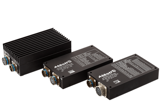 |
AM200 | 200 W | Sealed AC-DC, IP65/IP67, MS3470 connectors, power-factor-corrected input with integral EMI filtering | 95-260 Vac, 47-440 Hz, 1φ | Sealed airborne or multi-domain electronics needing controlled conducted and radiated emissions |
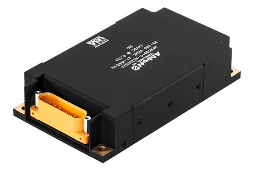 |
AS200 | 200 W | Rugged AC-DC, power-factor-corrected input with integral EMI filtering | 95-260 Vac, 47-440 Hz, 1φ | Rugged 200 W AC-DC conversion where full sealing is not required |
 |
CM500 | 500 W | Sealed AC-DC, IP65/IP67, MS3470 connectors; designed to meet MIL-STD-461 CE101 and CE102 | 95-260 Vac, 47-440 Hz, 1φ | Sealed 500 W AC applications with defined conducted-emissions limits |
 |
CS500 | 500 W | Rugged AC-DC, parallelable with single-wire current sharing, power-factor-corrected input with integral EMI filtering | 95-260 Vac, 47-440 Hz, 1φ | Higher-power regulated rails where rugged packaging and current sharing are required |
 |
CM1000 | 1000 W | Sealed AC-DC, power-factor-corrected input with integral EMI filtering | 95-260 Vac, 47-440 Hz, 1φ | Power-dense AC applications needing controlled emissions at 1000 W |
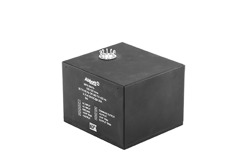 |
LPS | 12-210 W | Linear AC-DC; inherently low conducted and radiated switching noise; form-fit-function legacy replacement | 105-125 Vac, 55-65 Hz or 380-420 Hz, 1φ | Low-noise rails where switching emissions must be minimized, and legacy replacement |
Filtering note: where an existing supply or a piece of upstream equipment needs to be brought into compliance, an EMI filter or power-factor-corrected front end sized to the invoked CE101 and CE102 limits is often the shortest path. Abbott designs these to the application. Send the invoked methods, limits, and load, and our engineers will scope the right approach.
Getting the Selection Right
The hard part of MIL-STD-461 is rarely a single limit. It is engineering the emissions and susceptibility behavior into the supply and the installation so that the delivered configuration passes and stays passing.
- Design to the invoked method set, not a generic “meets 461.” A product that meets CE102 and RE102 for a ground application has not necessarily met the low-frequency magnetic requirements a submarine invokes. Confirm the methods and limit levels first.
- Treat the input EMI filter as part of the supply. Conducted emissions (CE101, CE102) are set by the filter, the topology, and the grounding together. A filter added downstream of an unfiltered module rarely recovers the margin, and good conducted-emissions margin tends to help radiated performance as well.
- Budget susceptibility margin, not just emissions. CS114, CS115, and CS116 require the supply to keep regulating through injected disturbances. Control-loop margin and holdup matter as much as filtering.
- Account for the revision G additions. CS117 lightning-induced transients and CS118 electrostatic discharge are newer requirements. Confirm whether your program invokes them, because they drive input protection and bonding.
- Keep emissions and susceptibility with the mechanical and thermal design. Shielding, bonding, gasketing, and connector selection interact with sealing, cooling, and vibration. Resolve them together, not in sequence.
- Radiated emissions depend on the installation, not only the unit. A supply that meets RE102 on its own can still push a system over the limit through cable routing, grounding, harness length, shield termination, and nearby equipment. The unit-level result is necessary but not sufficient; radiated compliance is usually won or lost in the integration, which is where a supplier who can adjust the unit to the installation is worth more than a fixed catalog part.
- Match the qualification configuration to the installed configuration. The filter, harness, connectors, backshells, and bonding used in the EMI test must match what is delivered, or the evidence does not transfer.
Selection Checklist
Define these items before you commit to a power supply for a MIL-STD-461 application:
| Requirement | What to define |
|---|---|
| Invoked standard | MIL-STD-461 revision (E, F, or G), the equipment specification, and any program-specific tailoring. |
| Applicable methods | The specific emissions and susceptibility methods invoked (for example CE102, RE102, CS114, CS115, CS116, RS103, and any CS117 or CS118). |
| Platform and installation | Aircraft, ground, surface ship, submarine, or space, and whether the installation is internal or exposed. |
| Limit levels | The specific limit curves and field strengths, since these are tailored by platform and by the equipment specification. |
| Input power type | 115 Vac, 230 Vac, 28 Vdc, 270 Vdc, single-phase or three-phase, fixed or variable frequency, which sets the emissions signature. |
| Architecture | DC-DC converter, single-phase AC-DC switcher, three-phase transformer rectifier unit, linear AC-DC, or a filter and front end ahead of existing equipment. |
| Filtering and bonding | Input EMI filter approach, shield termination, chassis bonding, grounding architecture, and connector and backshell selection. |
| Susceptibility margin | Required behavior during conducted and radiated susceptibility (operate through, degrade and recover, or no upset), and holdup or ride-through needs. |
| Transient and lightning | CS116, CS117, spike, and platform-level lightning or electromagnetic pulse requirements that drive input protection. |
| Thermal and mechanical | Sealing, cooling, shock, vibration, and mounting, since these interact with the EMI enclosure and bonding design. |
| Evidence package | EMI test report, analysis, similarity, or the test configuration required by the program. |
| Lifecycle support | Configuration control, obsolescence planning, and long-term availability of the EMI-critical parts. |
Integrating the Supply for EMI Compliance
A power supply designed to meet MIL-STD-461 still needs a disciplined installation. Treat the power entry and its EMI control as one subsystem:
- Place the EMI filter at the power entry, close to the enclosure boundary where it controls conducted emissions.
- Bond the supply and enclosure with a low-impedance path; EMI performance depends on the bonding, not only the filter.
- Terminate shields consistently at connectors and backshells; a shield grounded at one end only can undo radiated-emissions margin.
- Keep input power, output power, and low-level control or sense wiring separated where practical to limit coupling.
- Use the platform grounding and bonding approach; do not use the chassis as a power return unless the program architecture allows it.
- Route and clamp cables consistently, since CS114, CS115, and CS116 results depend on cable layout.
- Verify the delivered filter, harness, connectors, and bonding match the configuration used in the EMI qualification test.
The goal is to make the qualification configuration look like the installed configuration, so the EMI evidence holds in the field.
How Abbott Supports Your MIL-STD-461 Requirement
Abbott builds power conversion hardware for programs where electromagnetic compatibility, environmental survivability, configuration control, and lifecycle support all matter. Our AC-DC switchers integrate the input filtering and shielding needed to control conducted and radiated emissions, the LDC200 Series brings the same discipline to the 28 Vdc bus, the TR400 Series provides transformer-isolated three-phase AC-to-DC conversion with inherently low harmonic emissions, and the LPS Series offers an inherently low-noise linear alternative. Where the need is a filter or front end ahead of existing equipment, we design that to the invoked limits as well.
Because radiated compliance depends as much on the integration as on the unit, and because we design our own power electronics and maintain a large library of custom and modified power supply designs, we can modify a standard unit or tune its filter, shielding, and interfaces to meet the EMI requirement in your actual installation, not only on the bench. We configure standard products electrically and mechanically to fit the application, maintain full configuration control so the EMI-qualified configuration stays fixed, and support customers from consultation and prototyping through production and legacy sustainment. Abbott is AS9100 and ISO 9001 certified, and does not obsolete products without full consideration. MIL-STD-461 governs electromagnetic interference; for aircraft input power see our MIL-STD-704 guide, and for shipboard input power see our MIL-STD-1399 Section 300 guide.
Send us the invoked MIL-STD-461 revision and methods, the platform, the input power type, output rails, and required evidence package. Our application engineers will identify the right standard, modified, or custom power solution and its EMI approach. Contact us or complete the power supply design form.