
MIL-STD-1399 Power Supplies
Selecting AC-DC power supplies for shipboard power systems
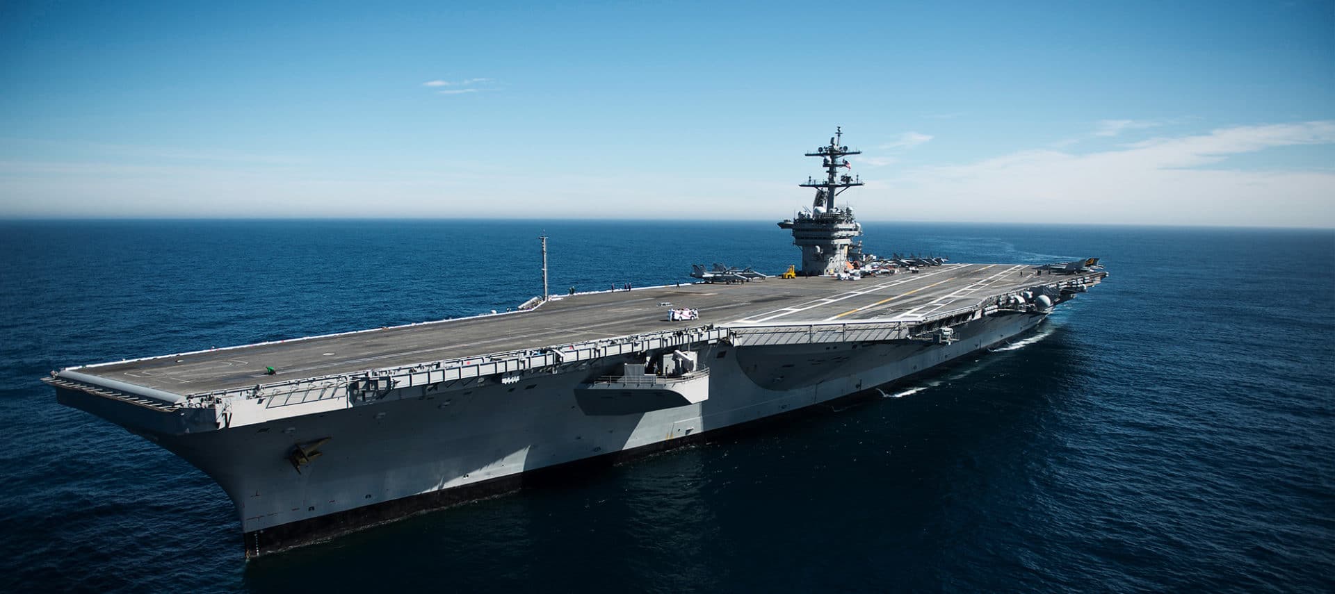
When you select an AC-DC power supply for shipboard equipment, the input source is not ordinary facility power. The supply becomes part of a shared electrical system, and its input behavior affects power quality, electromagnetic interference and compatibility, upstream protection, thermal design, and qualification results.
MIL-STD-1399 Section 300 defines the shipboard alternating-current power interface. For low-voltage AC shipboard power, the current document is MIL-STD-1399-300-1, Section 300, Part 1, Low Voltage Electric Power, Alternating Current. It establishes the interface requirements and constraints for user equipment connected to shipboard AC low-voltage power systems, including power-system characteristics, tolerances, and the test methods used to verify equipment compatibility.
Treating the standard as an interface requirement early, rather than a checkbox at qualification, is what keeps a program on schedule. This page explains what Section 300 asks of a power supply and helps you match your requirement to the right Abbott architecture.
What Section 300 Asks of Your Power Supply
Section 300 is an interface-control requirement. It does not simply tell you what nominal input voltage to expect. It defines how shipboard AC power behaves at the equipment interface, and how your equipment must behave as a load. For power conversion hardware, that affects:
| Design area | Why it matters |
|---|---|
| Input voltage and frequency | The supply must operate from the invoked shipboard AC power type, nominal voltage, frequency, and tolerance envelope. |
| Transients and interruptions | The input stage, protection circuit, control loop, and holdup strategy must be reviewed against the applicable abnormal-power cases. |
| Input current quality | Harmonic current, power factor, inrush current, and load dynamics can affect the shipboard bus and your qualification results. |
| EMI and EMC behavior | Section 300 does not replace MIL-STD-461. Conducted emissions, conducted susceptibility, shielding, grounding, and filtering are still engineered at the equipment level. |
| Mechanical and environmental survivability | Shipboard programs often combine Section 300 with shock, vibration, temperature, humidity, salt fog, ingress, and corrosion requirements. |
| Evidence and configuration control | The configuration you test must match the configuration you deliver. Changes to input filters, harnessing, grounding, connectors, or enclosure bonding can change the results. |
The practical takeaway: choose the supply as part of the shipboard power architecture, not as a late-stage commodity component.
MIL-STD-1399 Section 300 Power Characteristics (Quick Reference)
Section 300 Part 1 defines three power types and the tolerance envelope user equipment must accept. Type I is the standard 60 Hz shipboard power; Types II and III are 400 Hz, with Type III the precise, tighter-tolerance version used for avionics and aircraft servicing. Key characteristics from the standard’s Table II:
| Characteristic | Type I (60 Hz) | Type II (400 Hz) | Type III (400 Hz, precise) |
|---|---|---|---|
| Nominal frequency | 60 Hz | 400 Hz | 400 Hz |
| Nominal voltage | 440, 115, 115/200 Vrms | 440, 115 Vrms | 440, 115, 115/200 Vrms |
| Frequency tolerance | ±3% (submarines ±5%) | ±5% | ±0.5% |
| Worst-case frequency excursion | ±5.5% | ±6.5% | ±1.5% |
| Average line-to-line voltage tolerance | ±5% | ±5% | ±2% |
| Voltage transient tolerance | ±16% | ±16% | ±5% |
| Worst-case voltage excursion | ±20% | ±20% | ±5.5% |
| Transient recovery time | 2 s | 2 s | 0.25 s |
| Line-to-line voltage unbalance | 3% | 3% | 2% |
| Voltage spike (± peak) | 2.5 kV (440 V sys), 1.0 kV (115 V sys) | 2.5 kV / 1.0 kV | 2.5 kV / 1.0 kV |
| Max total harmonic distortion / single harmonic | 5% / 3% | 5% / 3% | 3% / 2% |
| Emergency excursion (voltage / frequency) | -100% to +35% / -100% to +12% | same | same |
Why a complete unit, not just a module: Section 300 is far more than a nominal voltage. The supply must ride through ±16% voltage and ±5.5% frequency transients and recover within 2 seconds, tolerate 2.5 kV peak voltage spikes riding on the line, hold input current distortion within limits, and survive emergency excursions to +35% voltage and down to complete loss. A bare converter gives you the regulator; a complete Abbott unit adds the input transient and spike protection, EMI filtering, and MIL-DTL-901 (formerly MIL-S-901) shock- and MIL-STD-167 vibration-qualified packaging needed to meet Section 300 in the installed configuration. Confirm the invoked Type (I, II, or III) and any platform tailoring, for example submarine or CVN 78 class, before finalizing the design.
Matching Input Coverage to Your Requirement
Several Abbott AC-DC switcher families accept a 95-260 Vac, 47-440 Hz single-phase input with power factor correction. That window covers the common nominal single-phase cases you meet across shipboard and military AC power: 115 Vac, 230 Vac, 60 Hz, and 400 Hz. One supply family therefore supports both 60 Hz (Type I) and 400 Hz (Type II/III) use cases without changing the AC input architecture.
The same wide-input architecture can help when equipment has adjacent requirements for aircraft AC power under MIL-STD-704. MIL-STD-704F includes 115/200 V at 400 Hz, variable-frequency 115/200 V from 360-800 Hz, 230/400 V at 400 Hz, and single-phase 115 V at 60 Hz for COTS-support applications. A 95-260 Vac, 47-440 Hz single-phase supply can support fixed-frequency 115 Vac or 230 Vac applications, but confirm the exact aircraft power type before treating it as a MIL-STD-704 solution, especially variable-frequency 360-800 Hz and three-phase interfaces. See our MIL-STD-704 AC power guide.
Abbott AC-DC Products for MIL-STD-1399 Section 300
Match your power level, output rails, and environment to a family below. Every single-phase switcher shares the 95-260 Vac, 47-440 Hz power-factor-corrected input, meets MIL-STD-1399 Section 300 Type 1, and is designed to meet MIL-DTL-901 (formerly MIL-S-901), MIL-STD-810, MIL-STD-704, and MIL-STD-461 (CE101/CE102). Outputs are factory-configurable.
| Series | Power | Configuration | Input | Output | Best for | |
|---|---|---|---|---|---|---|
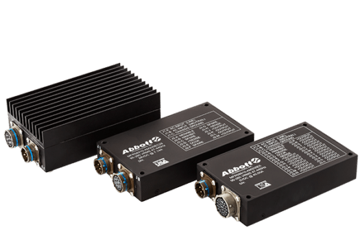 |
AM200 | 200 W | Sealed single-phase AC-DC (IP65/IP67, MS3470) | 95-260 Vac, 47-440 Hz, 1φ | Configurable DC | Distributed electronics, sensors, control assemblies, regulated DC rails |
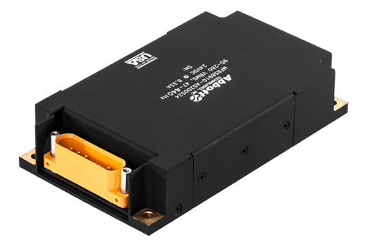 |
AS200 | 200 W | Rugged single-phase AC-DC | 95-260 Vac, 47-440 Hz, 1φ | Configurable DC | AM200 roles where full sealing is not required |
 |
CM500 | 500 W | Sealed single-phase AC-DC (IP65/IP67, MS3470) | 95-260 Vac, 47-440 Hz, 1φ | Configurable DC | Electronics drawers, communications, control systems |
 |
CS500 | 500 W | Rugged single-phase AC-DC, parallelable (single-wire current sharing) | 95-260 Vac, 47-440 Hz, 1φ | Configurable DC | Higher-power rails; parallel units for more power or redundancy |
 |
CM1000 | 1000 W | Sealed single-phase AC-DC | 95-260 Vac, 47-440 Hz, 1φ | Configurable DC | Power-dense assemblies; fewer converters and interconnects |
 |
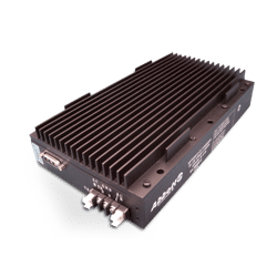
AR60 | 1-25 kW | 60 Hz three-phase AC to bulk DC; inherent harmonic suppression, passive PFC | 115/240/440 V delta, 60 Hz, 3φ | 24, 28, 280, 300 Vdc | Shipboard bulk DC, transformer-rectifier applications, battery charging |
 |
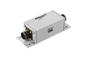
CL 110 PFC Front End | 500-1500 W | Active power factor correction front end | 115 V or universal | 190-450 Vdc | A dedicated PFC stage within a larger power architecture |
 |
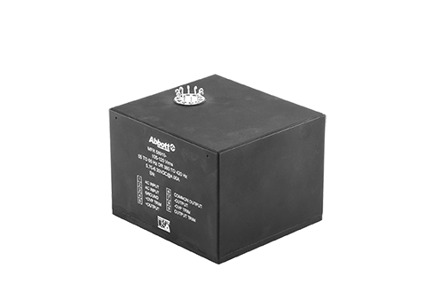
EMI Filters | Per application | Conducted-noise filters, single- and multi-phase AC and DC | Application-defined | Application-defined | Controlling conducted emissions and susceptibility at the power entry |
 |
LPS | Configurable | Linear AC-DC; form-fit-function legacy replacement | Configurable | Configurable | Low-noise linear rails; sustainment and DMSMS replacement of obsolete linear supplies |
Getting the Selection Right
The hard part of Section 300 compliance is rarely the nominal input voltage. It is ensuring the equipment behaves correctly across the full operating envelope and in the installed configuration.
- Design to the full Section 300 envelope, not the nominal voltage. The supply must ride through the voltage and frequency transients (±16% and ±5.5%, recovering within 2 seconds), tolerate the 2.5 kV line spike, and survive the emergency excursions above, not just operate at nominal 115 or 440 V.
- Size for the load, not the maximum. For three-phase transformer rectifiers and bulk converters such as the AR60, MIL-STD-1399 harmonic-current limits are defined relative to fundamental current at full load. Operating far below the converter’s rating can draw harmonic currents that exceed those limits relative to delivered power, so set the power rating around the real operating load profile rather than maximum nameplate margin.
- Engineer the installed configuration, not just the box. Conducted emissions and susceptibility depend on harness routing, shield terminations, connector backshells, chassis bonding, enclosure design, filter placement, and load distribution. Plan the MIL-STD-461 strategy at the equipment level, and keep the qualification configuration identical to the installed one.
- Match the claim to the evidence you need. “Designed to meet,” “meets,” and “qualified to” are not interchangeable. Confirm whether your program needs analysis, similarity, or a full qualification report, and Abbott will align the evidence package with that need.
Selection Checklist
Define these items before you commit to a supply:
| Requirement | What to define |
|---|---|
| Invoked standard | MIL-STD-1399 section, part, revision, type (I, II, or III), and any program-specific tailoring. |
| Input source | Single-phase or three-phase, nominal voltage, frequency, grounding method, and expected transient and interruption cases. |
| Output rails | Voltage, current, regulation, ripple and noise, sequencing, isolation, remote sense, and load-step behavior. |
| Load profile | Continuous, pulsed, intermittent, battery charging, motor-like, or highly capacitive. |
| Power margin | Actual operating load range, not only maximum theoretical load. Avoid oversizing where harmonic-current limits are load-dependent. |
| EMI strategy | MIL-STD-461 requirements, filter location, chassis bonding, shield termination, and harness routing. |
| Thermal path | Baseplate, chassis, forced air, water cooling, enclosure rise, and derating assumptions. |
| Mechanical environment | Shock, vibration, ingress, humidity, salt fog, mounting method, connectors, and maintainability. |
| Evidence package | Datasheet, analysis, similarity, qualification report, acceptance test procedure, burn-in, environmental stress screening, or custom test report. |
| Lifecycle support | Configuration control, obsolescence planning, replacement strategy, documentation control, and long-term availability. |
Integrating the Supply
A Section 300-compatible supply still needs a disciplined installation. Treat the power entry as an integrated subsystem:
- Keep input power, output power, and low-level control or sense wiring separated where practical.
- Bond the supply chassis to the equipment structure using the program grounding and bonding approach.
- Terminate shields consistently at connectors and backshells.
- Place EMI filters close to the power entry when they control conducted emissions at the enclosure boundary.
- Route remote-sense leads as a twisted pair, and connect them on the power-supply side of any output protection that can interrupt the DC output path.
- Verify thermal performance at the worst-case ambient, mounting orientation, load, and cooling condition.
The goal is to make the qualification configuration look like the installed configuration.
How Abbott Supports Your Program
Abbott builds power conversion hardware for programs where electrical performance, environmental survivability, configuration control, and lifecycle support all matter. We configure standard products electrically and mechanically to fit the application, maintain full configuration control, and support you from consultation and prototyping through production and legacy sustainment. Abbott is AS9100 and ISO 9001 certified, and does not obsolete products without full consideration.
Send us the invoked MIL-STD-1399 requirement, input power type, output rails, load profile, thermal and mechanical constraints, EMI requirements, and required evidence package, and our application engineers will identify the right standard, modified, or custom solution. Contact us or complete the power supply design form.