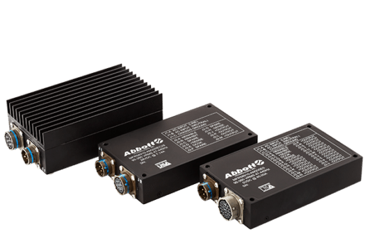
AM200 Series
- Category AC to DC Power Supplies
- Type Harsh Environment Switchers
- Power 200 Watts
High Efficiency, Compact Size, Customer Configurable.
Currently serving in many active programs with dozens of configurations, the AM200 Series features Power Factor Correction and is designed to perform in extreme environments. Designed to meet MIL-S-901 High Impact Shock and MIL-STD-810 Environmental Requirements, MIL-STD-704 and MIL-STD-1399 Input Requirements, MIL-STD-461 CE101, CE102 EMI Requirements (RE102 Compliant with Shielded Cables or Optional EMI Filter Output Connector).
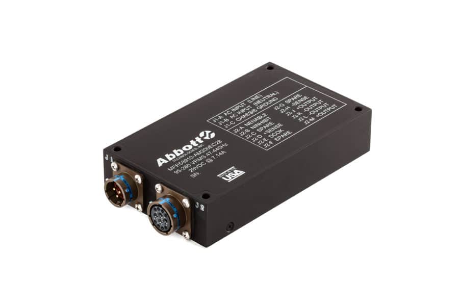
This series is IP65 sealed (IP67 available) and features MS3470 connectors as standard.
This series’ standard configuration features Over-Temperature Protection, Short Circuit Protection, Remote Error Sensing, Control Features, and Built-in Test Features.
This unit is Factory Configurable both electrically and mechanically to best fit your application.
Key Features
- Wide Input Range
- Power Factor Correction
- MIL-STD-1399 Section 300 Type 1 Requirements
- Sealed to Meet IP65 (IP67 Available)
- MIL-STD-461 CE101, CE102
- Fully Compliant with FCC 20780 Class A
- MIL-S-901 High Impact Shock
- MIL-STD-810 Environmental Requirements
- MIL-STD-167 Vibration Requirements
Specifications
- AC INPUT95-260 VAC, 47-440Hz, Single Phase
Power Factor Corrected
MIL-STD-1399, Section 300, Type 1 Requirements - EFFICIENCY80% Minimum (90% Typical, 28 VDC Model at 100% Load)
- LINE REGULATION±1% of Nominal over the Full Range of Line Input Voltage
- LOAD REGULATION±1% for Change from no Load to Full Load
- RIPPLE AND NOISEPeak-to-Peak Combined Ripple and Noise does not Exceed 2% of Nominal Output Measured with a 20 MHz Bandwidth
- INPUT TO OUTPUT1500 VDC
- INPUT TO CASE1500 VDC
- OUTPUT TO CASE500 VDC
- INPUT PROTECTIONInternal Fuse. In-rush current limiting.
- SHORT CIRCUIT PROTECTIONEach unit is completely protected against a short circuit of any duration. The current limit circuit nominally is set at 120% of full load to reduce voltage. The output voltage automatically restores to nominal when the short is removed
- REMOTE ERROR SENSINGStandard
- CONTROL FEATURESENABLE, INHIBIT (TTL LOW = TRUE)
Standard TTL, 3.3V Available upon Request - BUILT-IN TEST FEATUREDC OK
- Temperature Range
(No Power Derating)Storage, Transport and Handling:
-50°C to + 85°C
Ambient Temperature:
-40°C to 70°C
Baseplate Temperature:
-40°C to +70°C - Over-Temperature ProtectionOutput shut down if maximum case temperature limit is exceeded
- MEAN TIME BETWEEN FAILURE (MTBF)>100,000 Hours (calculated per MIL-HDBK-217Fn.2/25C/Full Load Ground Benign)
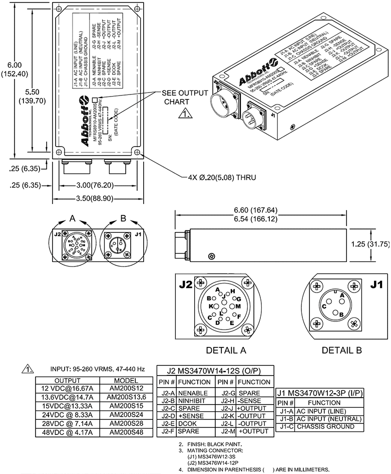
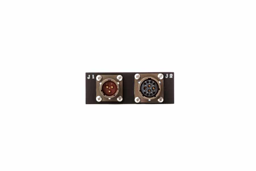
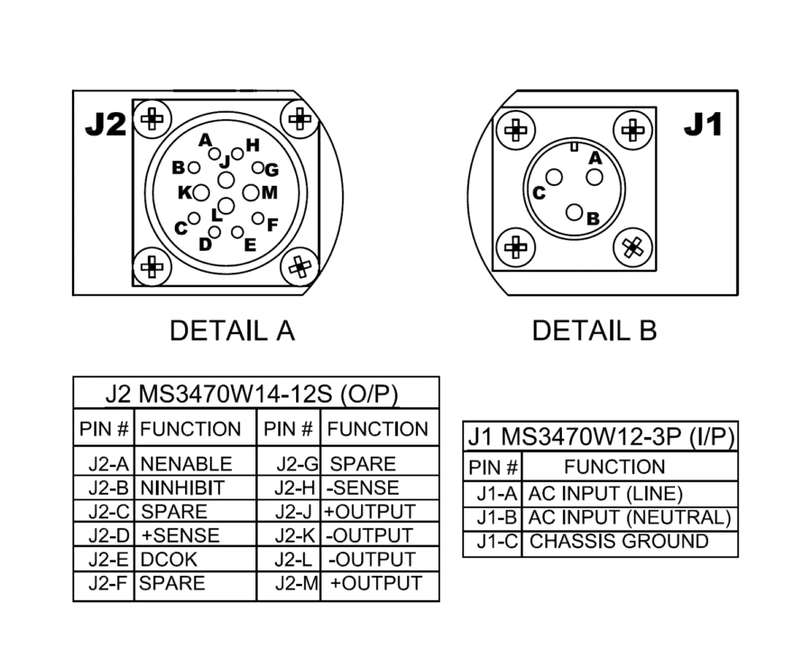
- CONNECTORSJ1 Input: MS3470W12-3P
J2 Output: MS3470W14-12S (Excluding 5V Model)
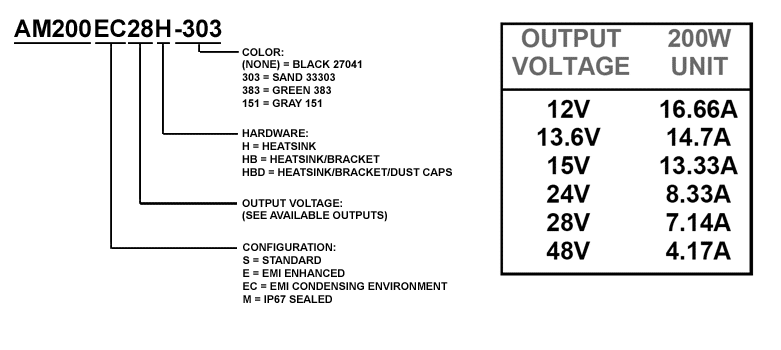
Electroless Nickel, PTFE, and Additional Connectors Available upon Request - STANDARD OUTPUTS (VDC)5, 12, 13.6, 15, 24, 28, 48 (Additional Voltages Available upon Request)
Options include Droop (Zero Wire) Current Sharing & Internal Oring Diode) - MATERIALSealed Aluminum Alloy 6061-T6 Case
- FINISHBlack 27041
Sand 33303
Green 383
Gray 151
Options include Heatsink, Mounting Bracket, and Dust Caps - ENVIRONMENTFully Sealed to Meet IP65, IP67 with M Configuration
MIL-S-901 (High Impact Shock)
MIL-STD-167 , Type 1 requirements
MIL-STD-810
Power supply operates without any evidence of degraded performance in non-condensing relative humidity up to 95%
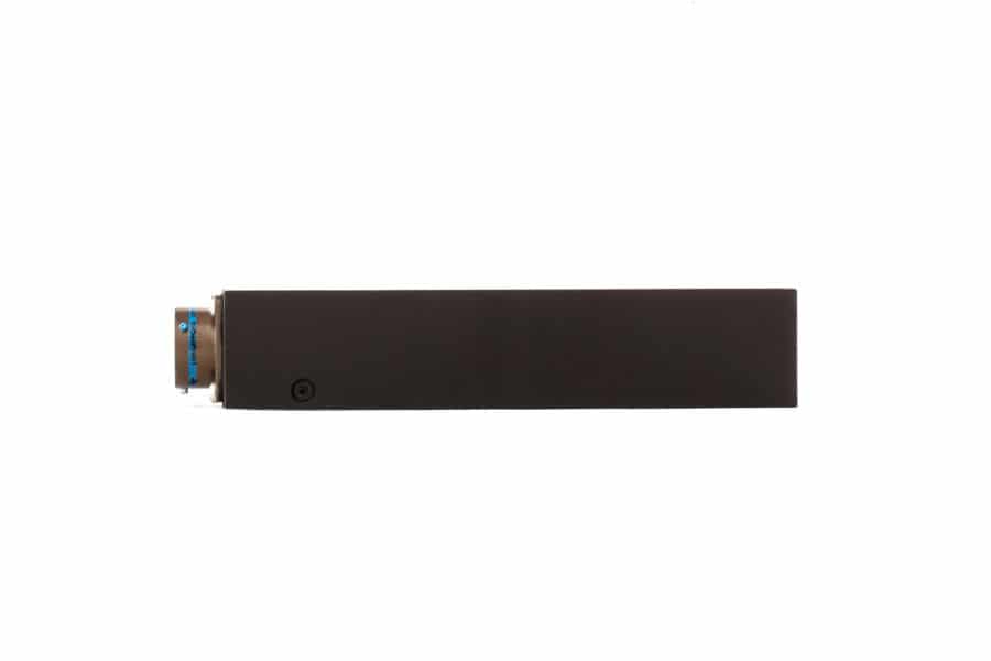
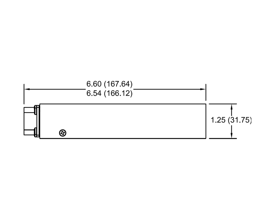
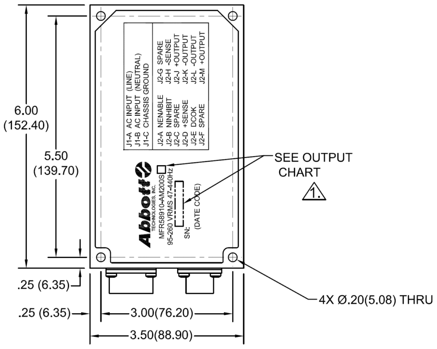
Mechanical Drawings
Naming Convention
Images

Have additional questions about the AM200 Series?
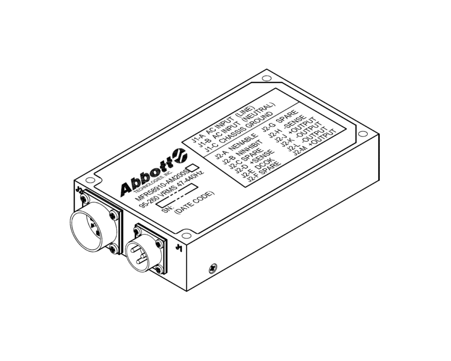
Speak with our Application EngineersAM200 Series Functions and Connections
- J1-C CHASSIS GROUNDInternally wired to chassis of unit.
- J2-A NENABLEEnables output of unit when pulled low.
- J2-B NIHIBITInhibits output of unit when pulled low.
- J2-C SPARENo Connection
- J2-D +SENSEPositive Sense Line provides point-of-use output voltage feedback signal to unit when tied to (+) side of output load to compensate for voltage drop of output cables under load.
(+) and (-) sense lines should be routed as a twisted pair to mitigate pickup of ambient electrical noise (EMI).
Sense lines must be connected on power supply side of any output protection devices, fuses, circuit breakers, switches, relays, etc which may interrupt DC Output Current Path. - J2-E DCOK+5VDC Signal when DC Output is within range. Pulls to active low (20mA maximum sink current) when DC Output is outside of Nominal Range.
Optional +3.3V, +12V signals available - J2-F SPARENo Connection
- J2-G SPARENo Connection
- J2-H -SENSENegative Sense Line (See J2-D above).
Available Model Listing
| Part Number | Output Voltage | Output Current | Configuration | Hardware | Finish | National Stock Number (NSN) | RFQ |
|---|---|---|---|---|---|---|---|
| AM200E12H-151 | 12 VDC | 16.67 A | EMI Enhanced | Heatsink | Haze Gray 151 | RFQ | |
| AM200E12H-303 | 12 VDC | 16.67 A | EMI Enhanced | Heatsink | 33303 Sand | RFQ | |
| AM200E12H-383 | 12 VDC | 16.67 A | EMI Enhanced | Heatsink | Green 383 | RFQ | |
| AM200E12H | 12 VDC | 16.67 A | EMI Enhanced | Heatsink | 27041 Black | RFQ | |
| AM200E12HB-151 | 12 VDC | 16.67 A | EMI Enhanced | Heatsink and Bracket | Haze Gray 151 | RFQ | |
| AM200E12HB-303 | 12 VDC | 16.67 A | EMI Enhanced | Heatsink and Bracket | 33303 Sand | RFQ | |
| AM200E12HB-383 | 12 VDC | 16.67 A | EMI Enhanced | Heatsink and Bracket | Green 383 | RFQ | |
| AM200E12HB | 12 VDC | 16.67 A | EMI Enhanced | Heatsink and Bracket | 27041 Black | RFQ | |
| AM200E12HBD-151 | 12 VDC | 16.67 A | EMI Enhanced | Heatsink, Bracket, and Dustcaps | Haze Gray 151 | RFQ | |
| AM200E12HBD-303 | 12 VDC | 16.67 A | EMI Enhanced | Heatsink, Bracket, and Dustcaps | 33303 Sand | RFQ | |
| AM200E12HBD-383 | 12 VDC | 16.67 A | EMI Enhanced | Heatsink, Bracket, and Dustcaps | Green 383 | RFQ | |
| AM200E12HBD | 12 VDC | 16.67 A | EMI Enhanced | Heatsink, Bracket, and Dustcaps | 27041 Black | RFQ | |
| AM200E12-151 | 12 VDC | 16.67 A | EMI Enhanced | None | Haze Gray 151 | RFQ | |
| AM200E12-303 | 12 VDC | 16.67 A | EMI Enhanced | None | 33303 Sand | RFQ | |
| AM200E12-383 | 12 VDC | 16.67 A | EMI Enhanced | None | Green 383 | RFQ | |
| AM200E12 | 12 VDC | 16.67 A | EMI Enhanced | None | 27041 Black | 6130-01-604-6434 | RFQ |
| AM200EC12H-151 | 12 VDC | 16.67 A | EMI Condensing Environment | Heatsink | Haze Gray 151 | RFQ | |
| AM200EC12H-303 | 12 VDC | 16.67 A | EMI Condensing Environment | Heatsink | 33303 Sand | RFQ | |
| AM200EC12H-383 | 12 VDC | 16.67 A | EMI Condensing Environment | Heatsink | Green 383 | RFQ | |
| AM200EC12H | 12 VDC | 16.67 A | EMI Condensing Environment | Heatsink | 27041 Black | RFQ | |
| AM200EC12HB-151 | 12 VDC | 16.67 A | EMI Condensing Environment | Heatsink and Bracket | Haze Gray 151 | RFQ | |
| AM200EC12HB-303 | 12 VDC | 16.67 A | EMI Condensing Environment | Heatsink and Bracket | 33303 Sand | RFQ | |
| AM200EC12HB-383 | 12 VDC | 16.67 A | EMI Condensing Environment | Heatsink and Bracket | Green 383 | RFQ | |
| AM200EC12HB | 12 VDC | 16.67 A | EMI Condensing Environment | Heatsink and Bracket | 27041 Black | RFQ | |
| AM200EC12HBD-151 | 12 VDC | 16.67 A | EMI Condensing Environment | Heatsink, Bracket, and Dustcaps | Haze Gray 151 | RFQ | |
| AM200EC12HBD-303 | 12 VDC | 16.67 A | EMI Condensing Environment | Heatsink, Bracket, and Dustcaps | 33303 Sand | RFQ | |
| AM200EC12HBD-383 | 12 VDC | 16.67 A | EMI Condensing Environment | Heatsink, Bracket, and Dustcaps | Green 383 | RFQ | |
| AM200EC12HBD | 12 VDC | 16.67 A | EMI Condensing Environment | Heatsink, Bracket, and Dustcaps | 27041 Black | RFQ | |
| AM200EC12-151 | 12 VDC | 16.67 A | EMI Condensing Environment | None | Haze Gray 151 | RFQ | |
| AM200EC12-303 | 12 VDC | 16.67 A | EMI Condensing Environment | None | 33303 Sand | RFQ | |
| AM200EC12-383 | 12 VDC | 16.67 A | EMI Condensing Environment | None | Green 383 | RFQ | |
| AM200EC12 | 12 VDC | 16.67 A | EMI Condensing Environment | None | 27041 Black | RFQ | |
| AM200M12H-151 | 12 VDC | 16.67 A | IP67 Sealed | Heatsink | Haze Gray 151 | RFQ | |
| AM200M12H-303 | 12 VDC | 16.67 A | IP67 Sealed | Heatsink | 33303 Sand | RFQ | |
| AM200M12H-383 | 12 VDC | 16.67 A | IP67 Sealed | Heatsink | Green 383 | RFQ | |
| AM200M12H | 12 VDC | 16.67 A | IP67 Sealed | Heatsink | 27041 Black | RFQ | |
| AM200M12HB-151 | 12 VDC | 16.67 A | IP67 Sealed | Heatsink and Bracket | Haze Gray 151 | RFQ | |
| AM200M12HB-303 | 12 VDC | 16.67 A | IP67 Sealed | Heatsink and Bracket | 33303 Sand | RFQ | |
| AM200M12HB-383 | 12 VDC | 16.67 A | IP67 Sealed | Heatsink and Bracket | Green 383 | RFQ | |
| AM200M12HB | 12 VDC | 16.67 A | IP67 Sealed | Heatsink and Bracket | 27041 Black | RFQ | |
| AM200M12HBD-151 | 12 VDC | 16.67 A | IP67 Sealed | Heatsink, Bracket, and Dustcaps | Haze Gray 151 | RFQ | |
| AM200M12HBD-303 | 12 VDC | 16.67 A | IP67 Sealed | Heatsink, Bracket, and Dustcaps | 33303 Sand | RFQ | |
| AM200M12HBD-383 | 12 VDC | 16.67 A | IP67 Sealed | Heatsink, Bracket, and Dustcaps | Green 383 | RFQ | |
| AM200M12HBD | 12 VDC | 16.67 A | IP67 Sealed | Heatsink, Bracket, and Dustcaps | 27041 Black | RFQ | |
| AM200M12-151 | 12 VDC | 16.67 A | IP67 Sealed | None | Haze Gray 151 | RFQ | |
| AM200M12-303 | 12 VDC | 16.67 A | IP67 Sealed | None | 33303 Sand | RFQ | |
| AM200M12-383 | 12 VDC | 16.67 A | IP67 Sealed | None | Green 383 | RFQ | |
| AM200M12 | 12 VDC | 16.67 A | IP67 Sealed | None | 27041 Black | RFQ | |
| AM200S12H-151 | 12 VDC | 16.67 A | Standard | Heatsink | Haze Gray 151 | RFQ | |
| AM200S12H-303 | 12 VDC | 16.67 A | Standard | Heatsink | 33303 Sand | RFQ | |
| AM200S12H-383 | 12 VDC | 16.67 A | Standard | Heatsink | Green 383 | RFQ | |
| AM200S12H | 12 VDC | 16.67 A | Standard | Heatsink | 27041 Black | RFQ | |
| AM200S12HB-151 | 12 VDC | 16.67 A | Standard | Heatsink and Bracket | Haze Gray 151 | RFQ | |
| AM200S12HB-303 | 12 VDC | 16.67 A | Standard | Heatsink and Bracket | 33303 Sand | RFQ | |
| AM200S12HB-383 | 12 VDC | 16.67 A | Standard | Heatsink and Bracket | Green 383 | RFQ | |
| AM200S12HB | 12 VDC | 16.67 A | Standard | Heatsink and Bracket | 27041 Black | RFQ | |
| AM200S12HBD-151 | 12 VDC | 16.67 A | Standard | Heatsink, Bracket, and Dustcaps | Haze Gray 151 | RFQ | |
| AM200S12HBD-303 | 12 VDC | 16.67 A | Standard | Heatsink, Bracket, and Dustcaps | 33303 Sand | RFQ | |
| AM200S12HBD-383 | 12 VDC | 16.67 A | Standard | Heatsink, Bracket, and Dustcaps | Green 383 | RFQ | |
| AM200S12HBD | 12 VDC | 16.67 A | Standard | Heatsink, Bracket, and Dustcaps | 27041 Black | RFQ | |
| AM200S12-151 | 12 VDC | 16.67 A | Standard | None | Haze Gray 151 | RFQ | |
| AM200S12-303 | 12 VDC | 16.67 A | Standard | None | 33303 Sand | RFQ | |
| AM200S12-383 | 12 VDC | 16.67 A | Standard | None | Green 383 | RFQ | |
| AM200S12 | 12 VDC | 16.67 A | Standard | None | 27041 Black | RFQ | |
| AM200E13.6H-151 | 13.6 VDC | 14.71 A | EMI Enhanced | Heatsink | Haze Gray 151 | RFQ | |
| AM200E13.6H-303 | 13.6 VDC | 14.71 A | EMI Enhanced | Heatsink | 33303 Sand | RFQ | |
| AM200E13.6H-383 | 13.6 VDC | 14.71 A | EMI Enhanced | Heatsink | Green 383 | RFQ | |
| AM200E13.6H | 13.6 VDC | 14.71 A | EMI Enhanced | Heatsink | 27041 Black | RFQ | |
| AM200E13.6HB-151 | 13.6 VDC | 14.71 A | EMI Enhanced | Heatsink and Bracket | Haze Gray 151 | RFQ | |
| AM200E13.6HB-303 | 13.6 VDC | 14.71 A | EMI Enhanced | Heatsink and Bracket | 33303 Sand | RFQ | |
| AM200E13.6HB-383 | 13.6 VDC | 14.71 A | EMI Enhanced | Heatsink and Bracket | Green 383 | RFQ | |
| AM200E13.6HB | 13.6 VDC | 14.71 A | EMI Enhanced | Heatsink and Bracket | 27041 Black | RFQ | |
| AM200E13.6HBD-151 | 13.6 VDC | 14.71 A | EMI Enhanced | Heatsink, Bracket, and Dustcaps | Haze Gray 151 | RFQ | |
| AM200E13.6HBD-303 | 13.6 VDC | 14.71 A | EMI Enhanced | Heatsink, Bracket, and Dustcaps | 33303 Sand | RFQ | |
| AM200E13.6HBD-383 | 13.6 VDC | 14.71 A | EMI Enhanced | Heatsink, Bracket, and Dustcaps | Green 383 | RFQ | |
| AM200E13.6HBD | 13.6 VDC | 14.71 A | EMI Enhanced | Heatsink, Bracket, and Dustcaps | 27041 Black | RFQ | |
| AM200E13.6-151 | 13.6 VDC | 14.71 A | EMI Enhanced | None | Haze Gray 151 | RFQ | |
| AM200E13.6-303 | 13.6 VDC | 14.71 A | EMI Enhanced | None | 33303 Sand | RFQ | |
| AM200E13.6-383 | 13.6 VDC | 14.71 A | EMI Enhanced | None | Green 383 | RFQ | |
| AM200E13.6 | 13.6 VDC | 14.71 A | EMI Enhanced | None | 27041 Black | RFQ | |
| AM200EC13.6H-151 | 13.6 VDC | 14.71 A | EMI Condensing Environment | Heatsink | Haze Gray 151 | RFQ | |
| AM200EC13.6H-303 | 13.6 VDC | 14.71 A | EMI Condensing Environment | Heatsink | 33303 Sand | RFQ | |
| AM200EC13.6H-383 | 13.6 VDC | 14.71 A | EMI Condensing Environment | Heatsink | Green 383 | RFQ | |
| AM200EC13.6H | 13.6 VDC | 14.71 A | EMI Condensing Environment | Heatsink | 27041 Black | RFQ | |
| AM200EC13.6HB-151 | 13.6 VDC | 14.71 A | EMI Condensing Environment | Heatsink and Bracket | Haze Gray 151 | RFQ | |
| AM200EC13.6HB-303 | 13.6 VDC | 14.71 A | EMI Condensing Environment | Heatsink and Bracket | 33303 Sand | RFQ | |
| AM200EC13.6HB-383 | 13.6 VDC | 14.71 A | EMI Condensing Environment | Heatsink and Bracket | Green 383 | RFQ | |
| AM200EC13.6HB | 13.6 VDC | 14.71 A | EMI Condensing Environment | Heatsink and Bracket | 27041 Black | RFQ | |
| AM200EC13.6HBD-151 | 13.6 VDC | 14.71 A | EMI Condensing Environment | Heatsink, Bracket, and Dustcaps | Haze Gray 151 | RFQ | |
| AM200EC13.6HBD-303 | 13.6 VDC | 14.71 A | EMI Condensing Environment | Heatsink, Bracket, and Dustcaps | 33303 Sand | RFQ | |
| AM200EC13.6HBD-383 | 13.6 VDC | 14.71 A | EMI Condensing Environment | Heatsink, Bracket, and Dustcaps | Green 383 | RFQ | |
| AM200EC13.6HBD | 13.6 VDC | 14.71 A | EMI Condensing Environment | Heatsink, Bracket, and Dustcaps | 27041 Black | RFQ | |
| AM200EC13.6-151 | 13.6 VDC | 14.71 A | EMI Condensing Environment | None | Haze Gray 151 | RFQ | |
| AM200EC13.6-303 | 13.6 VDC | 14.71 A | EMI Condensing Environment | None | 33303 Sand | RFQ | |
| AM200EC13.6-383 | 13.6 VDC | 14.71 A | EMI Condensing Environment | None | Green 383 | RFQ | |
| AM200EC13.6 | 13.6 VDC | 14.71 A | EMI Condensing Environment | None | 27041 Black | RFQ | |
| AM200M13.6H-151 | 13.6 VDC | 14.71 A | IP67 Sealed | Heatsink | Haze Gray 151 | RFQ | |
| AM200M13.6H-303 | 13.6 VDC | 14.71 A | IP67 Sealed | Heatsink | 33303 Sand | RFQ | |
| AM200M13.6H-383 | 13.6 VDC | 14.71 A | IP67 Sealed | Heatsink | Green 383 | RFQ | |
| AM200M13.6H | 13.6 VDC | 14.71 A | IP67 Sealed | Heatsink | 27041 Black | RFQ | |
| AM200M13.6HB-151 | 13.6 VDC | 14.71 A | IP67 Sealed | Heatsink and Bracket | Haze Gray 151 | RFQ | |
| AM200M13.6HB-303 | 13.6 VDC | 14.71 A | IP67 Sealed | Heatsink and Bracket | 33303 Sand | RFQ | |
| AM200M13.6HB-383 | 13.6 VDC | 14.71 A | IP67 Sealed | Heatsink and Bracket | Green 383 | RFQ | |
| AM200M13.6HB | 13.6 VDC | 14.71 A | IP67 Sealed | Heatsink and Bracket | 27041 Black | RFQ | |
| AM200M13.6HBD-151 | 13.6 VDC | 14.71 A | IP67 Sealed | Heatsink, Bracket, and Dustcaps | Haze Gray 151 | RFQ | |
| AM200M13.6HBD-303 | 13.6 VDC | 14.71 A | IP67 Sealed | Heatsink, Bracket, and Dustcaps | 33303 Sand | RFQ | |
| AM200M13.6HBD-383 | 13.6 VDC | 14.71 A | IP67 Sealed | Heatsink, Bracket, and Dustcaps | Green 383 | RFQ | |
| AM200M13.6HBD | 13.6 VDC | 14.71 A | IP67 Sealed | Heatsink, Bracket, and Dustcaps | 27041 Black | RFQ | |
| AM200M13.6-151 | 13.6 VDC | 14.71 A | IP67 Sealed | None | Haze Gray 151 | RFQ | |
| AM200M13.6-303 | 13.6 VDC | 14.71 A | IP67 Sealed | None | 33303 Sand | RFQ | |
| AM200M13.6-383 | 13.6 VDC | 14.71 A | IP67 Sealed | None | Green 383 | RFQ | |
| AM200M13.6 | 13.6 VDC | 14.71 A | IP67 Sealed | None | 27041 Black | RFQ | |
| AM200S13.6H-151 | 13.6 VDC | 14.71 A | Standard | Heatsink | Haze Gray 151 | RFQ | |
| AM200S13.6H-303 | 13.6 VDC | 14.71 A | Standard | Heatsink | 33303 Sand | RFQ | |
| AM200S13.6H-383 | 13.6 VDC | 14.71 A | Standard | Heatsink | Green 383 | RFQ | |
| AM200S13.6H | 13.6 VDC | 14.71 A | Standard | Heatsink | 27041 Black | RFQ | |
| AM200S13.6HB-151 | 13.6 VDC | 14.71 A | Standard | Heatsink and Bracket | Haze Gray 151 | RFQ | |
| AM200S13.6HB-303 | 13.6 VDC | 14.71 A | Standard | Heatsink and Bracket | 33303 Sand | RFQ | |
| AM200S13.6HB-383 | 13.6 VDC | 14.71 A | Standard | Heatsink and Bracket | Green 383 | RFQ | |
| AM200S13.6HB | 13.6 VDC | 14.71 A | Standard | Heatsink and Bracket | 27041 Black | RFQ | |
| AM200S13.6HBD-151 | 13.6 VDC | 14.71 A | Standard | Heatsink, Bracket, and Dustcaps | Haze Gray 151 | RFQ | |
| AM200S13.6HBD-303 | 13.6 VDC | 14.71 A | Standard | Heatsink, Bracket, and Dustcaps | 33303 Sand | RFQ | |
| AM200S13.6HBD-383 | 13.6 VDC | 14.71 A | Standard | Heatsink, Bracket, and Dustcaps | Green 383 | RFQ | |
| AM200S13.6HBD | 13.6 VDC | 14.71 A | Standard | Heatsink, Bracket, and Dustcaps | 27041 Black | RFQ | |
| AM200S13.6-151 | 13.6 VDC | 14.71 A | Standard | None | Haze Gray 151 | RFQ | |
| AM200S13.6-303 | 13.6 VDC | 14.71 A | Standard | None | 33303 Sand | RFQ | |
| AM200S13.6-383 | 13.6 VDC | 14.71 A | Standard | None | Green 383 | RFQ | |
| AM200S13.6 | 13.6 VDC | 14.71 A | Standard | None | 27041 Black | RFQ | |
| AM200E15H-151 | 15 VDC | 13.33 A | EMI Enhanced | Heatsink | Haze Gray 151 | RFQ | |
| AM200E15H-303 | 15 VDC | 13.33 A | EMI Enhanced | Heatsink | 33303 Sand | RFQ | |
| AM200E15H-383 | 15 VDC | 13.33 A | EMI Enhanced | Heatsink | Green 383 | RFQ | |
| AM200E15H | 15 VDC | 13.33 A | EMI Enhanced | Heatsink | 27041 Black | RFQ | |
| AM200E15HB-151 | 15 VDC | 13.33 A | EMI Enhanced | Heatsink and Bracket | Haze Gray 151 | RFQ | |
| AM200E15HB-303 | 15 VDC | 13.33 A | EMI Enhanced | Heatsink and Bracket | 33303 Sand | RFQ | |
| AM200E15HB-383 | 15 VDC | 13.33 A | EMI Enhanced | Heatsink and Bracket | Green 383 | RFQ | |
| AM200E15HB | 15 VDC | 13.33 A | EMI Enhanced | Heatsink and Bracket | 27041 Black | RFQ | |
| AM200E15HBD-151 | 15 VDC | 13.33 A | EMI Enhanced | Heatsink, Bracket, and Dustcaps | Haze Gray 151 | RFQ | |
| AM200E15HBD-303 | 15 VDC | 13.33 A | EMI Enhanced | Heatsink, Bracket, and Dustcaps | 33303 Sand | RFQ | |
| AM200E15HBD-383 | 15 VDC | 13.33 A | EMI Enhanced | Heatsink, Bracket, and Dustcaps | Green 383 | RFQ | |
| AM200E15HBD | 15 VDC | 13.33 A | EMI Enhanced | Heatsink, Bracket, and Dustcaps | 27041 Black | RFQ | |
| AM200E15-151 | 15 VDC | 13.33 A | EMI Enhanced | None | Haze Gray 151 | RFQ | |
| AM200E15-303 | 15 VDC | 13.33 A | EMI Enhanced | None | 33303 Sand | RFQ | |
| AM200E15-383 | 15 VDC | 13.33 A | EMI Enhanced | None | Green 383 | RFQ | |
| AM200E15 | 15 VDC | 13.33 A | EMI Enhanced | None | 27041 Black | RFQ | |
| AM200EC15H-151 | 15 VDC | 13.33 A | EMI Condensing Environment | Heatsink | Haze Gray 151 | RFQ | |
| AM200EC15H-303 | 15 VDC | 13.33 A | EMI Condensing Environment | Heatsink | 33303 Sand | RFQ | |
| AM200EC15H-383 | 15 VDC | 13.33 A | EMI Condensing Environment | Heatsink | Green 383 | RFQ | |
| AM200EC15H | 15 VDC | 13.33 A | EMI Condensing Environment | Heatsink | 27041 Black | RFQ | |
| AM200EC15HB-151 | 15 VDC | 13.33 A | EMI Condensing Environment | Heatsink and Bracket | Haze Gray 151 | RFQ | |
| AM200EC15HB-303 | 15 VDC | 13.33 A | EMI Condensing Environment | Heatsink and Bracket | 33303 Sand | RFQ | |
| AM200EC15HB-383 | 15 VDC | 13.33 A | EMI Condensing Environment | Heatsink and Bracket | Green 383 | RFQ | |
| AM200EC15HB | 15 VDC | 13.33 A | EMI Condensing Environment | Heatsink and Bracket | 27041 Black | RFQ | |
| AM200EC15HBD-151 | 15 VDC | 13.33 A | EMI Condensing Environment | Heatsink, Bracket, and Dustcaps | Haze Gray 151 | RFQ | |
| AM200EC15HBD-303 | 15 VDC | 13.33 A | EMI Condensing Environment | Heatsink, Bracket, and Dustcaps | 33303 Sand | RFQ | |
| AM200EC15HBD-383 | 15 VDC | 13.33 A | EMI Condensing Environment | Heatsink, Bracket, and Dustcaps | Green 383 | RFQ | |
| AM200EC15HBD | 15 VDC | 13.33 A | EMI Condensing Environment | Heatsink, Bracket, and Dustcaps | 27041 Black | RFQ | |
| AM200EC15-151 | 15 VDC | 13.33 A | EMI Condensing Environment | None | Haze Gray 151 | RFQ | |
| AM200EC15-303 | 15 VDC | 13.33 A | EMI Condensing Environment | None | 33303 Sand | RFQ | |
| AM200EC15-383 | 15 VDC | 13.33 A | EMI Condensing Environment | None | Green 383 | RFQ | |
| AM200EC15 | 15 VDC | 13.33 A | EMI Condensing Environment | None | 27041 Black | 6130-01-618-4200 | RFQ |
| AM200M15H-151 | 15 VDC | 13.33 A | IP67 Sealed | Heatsink | Haze Gray 151 | RFQ | |
| AM200M15H-303 | 15 VDC | 13.33 A | IP67 Sealed | Heatsink | 33303 Sand | RFQ | |
| AM200M15H-383 | 15 VDC | 13.33 A | IP67 Sealed | Heatsink | Green 383 | RFQ | |
| AM200M15H | 15 VDC | 13.33 A | IP67 Sealed | Heatsink | 27041 Black | RFQ | |
| AM200M15HB-151 | 15 VDC | 13.33 A | IP67 Sealed | Heatsink and Bracket | Haze Gray 151 | RFQ | |
| AM200M15HB-303 | 15 VDC | 13.33 A | IP67 Sealed | Heatsink and Bracket | 33303 Sand | RFQ | |
| AM200M15HB-383 | 15 VDC | 13.33 A | IP67 Sealed | Heatsink and Bracket | Green 383 | RFQ | |
| AM200M15HB | 15 VDC | 13.33 A | IP67 Sealed | Heatsink and Bracket | 27041 Black | RFQ | |
| AM200M15HBD-151 | 15 VDC | 13.33 A | IP67 Sealed | Heatsink, Bracket, and Dustcaps | Haze Gray 151 | RFQ | |
| AM200M15HBD-303 | 15 VDC | 13.33 A | IP67 Sealed | Heatsink, Bracket, and Dustcaps | 33303 Sand | RFQ | |
| AM200M15HBD-383 | 15 VDC | 13.33 A | IP67 Sealed | Heatsink, Bracket, and Dustcaps | Green 383 | RFQ | |
| AM200M15HBD | 15 VDC | 13.33 A | IP67 Sealed | Heatsink, Bracket, and Dustcaps | 27041 Black | RFQ | |
| AM200M15-151 | 15 VDC | 13.33 A | IP67 Sealed | None | Haze Gray 151 | RFQ | |
| AM200M15-303 | 15 VDC | 13.33 A | IP67 Sealed | None | 33303 Sand | RFQ | |
| AM200M15-383 | 15 VDC | 13.33 A | IP67 Sealed | None | Green 383 | RFQ | |
| AM200M15 | 15 VDC | 13.33 A | IP67 Sealed | None | 27041 Black | RFQ | |
| AM200S15H-151 | 15 VDC | 13.33 A | Standard | Heatsink | Haze Gray 151 | RFQ | |
| AM200S15H-303 | 15 VDC | 13.33 A | Standard | Heatsink | 33303 Sand | RFQ | |
| AM200S15H-383 | 15 VDC | 13.33 A | Standard | Heatsink | Green 383 | RFQ | |
| AM200S15H | 15 VDC | 13.33 A | Standard | Heatsink | 27041 Black | RFQ | |
| AM200S15HB-151 | 15 VDC | 13.33 A | Standard | Heatsink and Bracket | Haze Gray 151 | RFQ | |
| AM200S15HB-303 | 15 VDC | 13.33 A | Standard | Heatsink and Bracket | 33303 Sand | RFQ | |
| AM200S15HB-383 | 15 VDC | 13.33 A | Standard | Heatsink and Bracket | Green 383 | RFQ | |
| AM200S15HB | 15 VDC | 13.33 A | Standard | Heatsink and Bracket | 27041 Black | RFQ | |
| AM200S15HBD-151 | 15 VDC | 13.33 A | Standard | Heatsink, Bracket, and Dustcaps | Haze Gray 151 | RFQ | |
| AM200S15HBD-303 | 15 VDC | 13.33 A | Standard | Heatsink, Bracket, and Dustcaps | 33303 Sand | RFQ | |
| AM200S15HBD-383 | 15 VDC | 13.33 A | Standard | Heatsink, Bracket, and Dustcaps | Green 383 | RFQ | |
| AM200S15HBD | 15 VDC | 13.33 A | Standard | Heatsink, Bracket, and Dustcaps | 27041 Black | RFQ | |
| AM200S15-151 | 15 VDC | 13.33 A | Standard | None | Haze Gray 151 | RFQ | |
| AM200S15-303 | 15 VDC | 13.33 A | Standard | None | 33303 Sand | RFQ | |
| AM200S15-383 | 15 VDC | 13.33 A | Standard | None | Green 383 | RFQ | |
| AM200S15 | 15 VDC | 13.33 A | Standard | None | 27041 Black | 1560-01-604-0550 | RFQ |
| AM200E24H-151 | 24 VDC | 8.33 A | EMI Enhanced | Heatsink | Haze Gray 151 | RFQ | |
| AM200E24H-303 | 24 VDC | 8.33 A | EMI Enhanced | Heatsink | 33303 Sand | RFQ | |
| AM200E24H-383 | 24 VDC | 8.33 A | EMI Enhanced | Heatsink | Green 383 | RFQ | |
| AM200E24H | 24 VDC | 8.33 A | EMI Enhanced | Heatsink | 27041 Black | RFQ | |
| AM200E24HB-151 | 24 VDC | 8.33 A | EMI Enhanced | Heatsink and Bracket | Haze Gray 151 | RFQ | |
| AM200E24HB-303 | 24 VDC | 8.33 A | EMI Enhanced | Heatsink and Bracket | 33303 Sand | RFQ | |
| AM200E24HB-383 | 24 VDC | 8.33 A | EMI Enhanced | Heatsink and Bracket | Green 383 | RFQ | |
| AM200E24HB | 24 VDC | 8.33 A | EMI Enhanced | Heatsink and Bracket | 27041 Black | RFQ | |
| AM200E24HBD-151 | 24 VDC | 8.33 A | EMI Enhanced | Heatsink, Bracket, and Dustcaps | Haze Gray 151 | RFQ | |
| AM200E24HBD-303 | 24 VDC | 8.33 A | EMI Enhanced | Heatsink, Bracket, and Dustcaps | 33303 Sand | RFQ | |
| AM200E24HBD-383 | 24 VDC | 8.33 A | EMI Enhanced | Heatsink, Bracket, and Dustcaps | Green 383 | RFQ | |
| AM200E24HBD | 24 VDC | 8.33 A | EMI Enhanced | Heatsink, Bracket, and Dustcaps | 27041 Black | RFQ | |
| AM200E24-151 | 24 VDC | 8.33 A | EMI Enhanced | None | Haze Gray 151 | RFQ | |
| AM200E24-303 | 24 VDC | 8.33 A | EMI Enhanced | None | 33303 Sand | RFQ | |
| AM200E24-383 | 24 VDC | 8.33 A | EMI Enhanced | None | Green 383 | RFQ | |
| AM200E24 | 24 VDC | 8.33 A | EMI Enhanced | None | 27041 Black | RFQ | |
| AM200EC24H-151 | 24 VDC | 8.33 A | EMI Condensing Environment | Heatsink | Haze Gray 151 | RFQ | |
| AM200EC24H-303 | 24 VDC | 8.33 A | EMI Condensing Environment | Heatsink | 33303 Sand | RFQ | |
| AM200EC24H-383 | 24 VDC | 8.33 A | EMI Condensing Environment | Heatsink | Green 383 | RFQ | |
| AM200EC24H | 24 VDC | 8.33 A | EMI Condensing Environment | Heatsink | 27041 Black | RFQ | |
| AM200EC24HB-151 | 24 VDC | 8.33 A | EMI Condensing Environment | Heatsink and Bracket | Haze Gray 151 | RFQ | |
| AM200EC24HB-303 | 24 VDC | 8.33 A | EMI Condensing Environment | Heatsink and Bracket | 33303 Sand | RFQ | |
| AM200EC24HB-383 | 24 VDC | 8.33 A | EMI Condensing Environment | Heatsink and Bracket | Green 383 | RFQ | |
| AM200EC24HB | 24 VDC | 8.33 A | EMI Condensing Environment | Heatsink and Bracket | 27041 Black | RFQ | |
| AM200EC24HBD-151 | 24 VDC | 8.33 A | EMI Condensing Environment | Heatsink, Bracket, and Dustcaps | Haze Gray 151 | RFQ | |
| AM200EC24HBD-303 | 24 VDC | 8.33 A | EMI Condensing Environment | Heatsink, Bracket, and Dustcaps | 33303 Sand | RFQ | |
| AM200EC24HBD-383 | 24 VDC | 8.33 A | EMI Condensing Environment | Heatsink, Bracket, and Dustcaps | Green 383 | RFQ | |
| AM200EC24HBD | 24 VDC | 8.33 A | EMI Condensing Environment | Heatsink, Bracket, and Dustcaps | 27041 Black | RFQ | |
| AM200EC24-151 | 24 VDC | 8.33 A | EMI Condensing Environment | None | Haze Gray 151 | RFQ | |
| AM200EC24-303 | 24 VDC | 8.33 A | EMI Condensing Environment | None | 33303 Sand | RFQ | |
| AM200EC24-383 | 24 VDC | 8.33 A | EMI Condensing Environment | None | Green 383 | RFQ | |
| AM200EC24 | 24 VDC | 8.33 A | EMI Condensing Environment | None | 27041 Black | RFQ | |
| AM200M24H-151 | 24 VDC | 8.33 A | IP67 Sealed | Heatsink | Haze Gray 151 | RFQ | |
| AM200M24H-303 | 24 VDC | 8.33 A | IP67 Sealed | Heatsink | 33303 Sand | RFQ | |
| AM200M24H-383 | 24 VDC | 8.33 A | IP67 Sealed | Heatsink | Green 383 | RFQ | |
| AM200M24H | 24 VDC | 8.33 A | IP67 Sealed | Heatsink | 27041 Black | RFQ | |
| AM200M24HB-151 | 24 VDC | 8.33 A | IP67 Sealed | Heatsink and Bracket | Haze Gray 151 | RFQ | |
| AM200M24HB-303 | 24 VDC | 8.33 A | IP67 Sealed | Heatsink and Bracket | 33303 Sand | RFQ | |
| AM200M24HB-383 | 24 VDC | 8.33 A | IP67 Sealed | Heatsink and Bracket | Green 383 | RFQ | |
| AM200M24HB | 24 VDC | 8.33 A | IP67 Sealed | Heatsink and Bracket | 27041 Black | RFQ | |
| AM200M24HBD-151 | 24 VDC | 8.33 A | IP67 Sealed | Heatsink, Bracket, and Dustcaps | Haze Gray 151 | RFQ | |
| AM200M24HBD-303 | 24 VDC | 8.33 A | IP67 Sealed | Heatsink, Bracket, and Dustcaps | 33303 Sand | RFQ | |
| AM200M24HBD-383 | 24 VDC | 8.33 A | IP67 Sealed | Heatsink, Bracket, and Dustcaps | Green 383 | RFQ | |
| AM200M24HBD | 24 VDC | 8.33 A | IP67 Sealed | Heatsink, Bracket, and Dustcaps | 27041 Black | RFQ | |
| AM200M24-151 | 24 VDC | 8.33 A | IP67 Sealed | None | Haze Gray 151 | RFQ | |
| AM200M24-303 | 24 VDC | 8.33 A | IP67 Sealed | None | 33303 Sand | RFQ | |
| AM200M24-383 | 24 VDC | 8.33 A | IP67 Sealed | None | Green 383 | RFQ | |
| AM200M24 | 24 VDC | 8.33 A | IP67 Sealed | None | 27041 Black | RFQ | |
| AM200S24H-151 | 24 VDC | 8.33 A | Standard | Heatsink | Haze Gray 151 | RFQ | |
| AM200S24H-303 | 24 VDC | 8.33 A | Standard | Heatsink | 33303 Sand | RFQ | |
| AM200S24H-383 | 24 VDC | 8.33 A | Standard | Heatsink | Green 383 | RFQ | |
| AM200S24H | 24 VDC | 8.33 A | Standard | Heatsink | 27041 Black | RFQ | |
| AM200S24HB-151 | 24 VDC | 8.33 A | Standard | Heatsink and Bracket | Haze Gray 151 | RFQ | |
| AM200S24HB-303 | 24 VDC | 8.33 A | Standard | Heatsink and Bracket | 33303 Sand | RFQ | |
| AM200S24HB-383 | 24 VDC | 8.33 A | Standard | Heatsink and Bracket | Green 383 | RFQ | |
| AM200S24HB | 24 VDC | 8.33 A | Standard | Heatsink and Bracket | 27041 Black | RFQ | |
| AM200S24HBD-151 | 24 VDC | 8.33 A | Standard | Heatsink, Bracket, and Dustcaps | Haze Gray 151 | RFQ | |
| AM200S24HBD-303 | 24 VDC | 8.33 A | Standard | Heatsink, Bracket, and Dustcaps | 33303 Sand | RFQ | |
| AM200S24HBD-383 | 24 VDC | 8.33 A | Standard | Heatsink, Bracket, and Dustcaps | Green 383 | RFQ | |
| AM200S24HBD | 24 VDC | 8.33 A | Standard | Heatsink, Bracket, and Dustcaps | 27041 Black | RFQ | |
| AM200S24-151 | 24 VDC | 8.33 A | Standard | None | Haze Gray 151 | RFQ | |
| AM200S24-303 | 24 VDC | 8.33 A | Standard | None | 33303 Sand | RFQ | |
| AM200S24-383 | 24 VDC | 8.33 A | Standard | None | Green 383 | RFQ | |
| AM200S24 | 24 VDC | 8.33 A | Standard | None | 27041 Black | RFQ | |
| AM200E28H-151 | 28 VDC | 7.14 A | EMI Enhanced | Heatsink | Haze Gray 151 | RFQ | |
| AM200E28H-303 | 28 VDC | 7.14 A | EMI Enhanced | Heatsink | 33303 Sand | RFQ | |
| AM200E28H-383 | 28 VDC | 7.14 A | EMI Enhanced | Heatsink | Green 383 | RFQ | |
| AM200E28H | 28 VDC | 7.14 A | EMI Enhanced | Heatsink | 27041 Black | RFQ | |
| AM200E28HB-151 | 28 VDC | 7.14 A | EMI Enhanced | Heatsink and Bracket | Haze Gray 151 | RFQ | |
| AM200E28HB-303 | 28 VDC | 7.14 A | EMI Enhanced | Heatsink and Bracket | 33303 Sand | RFQ | |
| AM200E28HB-383 | 28 VDC | 7.14 A | EMI Enhanced | Heatsink and Bracket | Green 383 | RFQ | |
| AM200E28HB | 28 VDC | 7.14 A | EMI Enhanced | Heatsink and Bracket | 27041 Black | RFQ | |
| AM200E28HBD-151 | 28 VDC | 7.14 A | EMI Enhanced | Heatsink, Bracket, and Dustcaps | Haze Gray 151 | RFQ | |
| AM200E28HBD-303 | 28 VDC | 7.14 A | EMI Enhanced | Heatsink, Bracket, and Dustcaps | 33303 Sand | RFQ | |
| AM200E28HBD-383 | 28 VDC | 7.14 A | EMI Enhanced | Heatsink, Bracket, and Dustcaps | Green 383 | RFQ | |
| AM200E28HBD | 28 VDC | 7.14 A | EMI Enhanced | Heatsink, Bracket, and Dustcaps | 27041 Black | RFQ | |
| AM200E28-151 | 28 VDC | 7.14 A | EMI Enhanced | None | Haze Gray 151 | RFQ | |
| AM200E28-303 | 28 VDC | 7.14 A | EMI Enhanced | None | 33303 Sand | RFQ | |
| AM200E28-383 | 28 VDC | 7.14 A | EMI Enhanced | None | Green 383 | RFQ | |
| AM200E28 | 28 VDC | 7.14 A | EMI Enhanced | None | 27041 Black | RFQ | |
| AM200EC28H-151 | 28 VDC | 7.14 A | EMI Condensing Environment | Heatsink | Haze Gray 151 | RFQ | |
| AM200EC28H-303 | 28 VDC | 7.14 A | EMI Condensing Environment | Heatsink | 33303 Sand | RFQ | |
| AM200EC28H-383 | 28 VDC | 7.14 A | EMI Condensing Environment | Heatsink | Green 383 | RFQ | |
| AM200EC28H | 28 VDC | 7.14 A | EMI Condensing Environment | Heatsink | 27041 Black | RFQ | |
| AM200EC28HB-151 | 28 VDC | 7.14 A | EMI Condensing Environment | Heatsink and Bracket | Haze Gray 151 | RFQ | |
| AM200EC28HB-303 | 28 VDC | 7.14 A | EMI Condensing Environment | Heatsink and Bracket | 33303 Sand | RFQ | |
| AM200EC28HB-383 | 28 VDC | 7.14 A | EMI Condensing Environment | Heatsink and Bracket | Green 383 | RFQ | |
| AM200EC28HB | 28 VDC | 7.14 A | EMI Condensing Environment | Heatsink and Bracket | 27041 Black | RFQ | |
| AM200EC28HBD-151 | 28 VDC | 7.14 A | EMI Condensing Environment | Heatsink, Bracket, and Dustcaps | Haze Gray 151 | RFQ | |
| AM200EC28HBD-303 | 28 VDC | 7.14 A | EMI Condensing Environment | Heatsink, Bracket, and Dustcaps | 33303 Sand | RFQ | |
| AM200EC28HBD-383 | 28 VDC | 7.14 A | EMI Condensing Environment | Heatsink, Bracket, and Dustcaps | Green 383 | RFQ | |
| AM200EC28HBD | 28 VDC | 7.14 A | EMI Condensing Environment | Heatsink, Bracket, and Dustcaps | 27041 Black | RFQ | |
| AM200EC28-151 | 28 VDC | 7.14 A | EMI Condensing Environment | None | Haze Gray 151 | RFQ | |
| AM200EC28-303 | 28 VDC | 7.14 A | EMI Condensing Environment | None | 33303 Sand | RFQ | |
| AM200EC28-383 | 28 VDC | 7.14 A | EMI Condensing Environment | None | Green 383 | RFQ | |
| AM200EC28 | 28 VDC | 7.14 A | EMI Condensing Environment | None | 27041 Black | 6130-01-619-3888 | RFQ |
| AM200M28H-151 | 28 VDC | 7.14 A | IP67 Sealed | Heatsink | Haze Gray 151 | RFQ | |
| AM200M28H-303 | 28 VDC | 7.14 A | IP67 Sealed | Heatsink | 33303 Sand | RFQ | |
| AM200M28H-383 | 28 VDC | 7.14 A | IP67 Sealed | Heatsink | Green 383 | RFQ | |
| AM200M28H | 28 VDC | 7.14 A | IP67 Sealed | Heatsink | 27041 Black | RFQ | |
| AM200M28HB-151 | 28 VDC | 7.14 A | IP67 Sealed | Heatsink and Bracket | Haze Gray 151 | RFQ | |
| AM200M28HB-303 | 28 VDC | 7.14 A | IP67 Sealed | Heatsink and Bracket | 33303 Sand | RFQ | |
| AM200M28HB-383 | 28 VDC | 7.14 A | IP67 Sealed | Heatsink and Bracket | Green 383 | RFQ | |
| AM200M28HB | 28 VDC | 7.14 A | IP67 Sealed | Heatsink and Bracket | 27041 Black | RFQ | |
| AM200M28HBD-151 | 28 VDC | 7.14 A | IP67 Sealed | Heatsink, Bracket, and Dustcaps | Haze Gray 151 | RFQ | |
| AM200M28HBD-303 | 28 VDC | 7.14 A | IP67 Sealed | Heatsink, Bracket, and Dustcaps | 33303 Sand | RFQ | |
| AM200M28HBD-383 | 28 VDC | 7.14 A | IP67 Sealed | Heatsink, Bracket, and Dustcaps | Green 383 | RFQ | |
| AM200M28HBD | 28 VDC | 7.14 A | IP67 Sealed | Heatsink, Bracket, and Dustcaps | 27041 Black | RFQ | |
| AM200M28-151 | 28 VDC | 7.14 A | IP67 Sealed | None | Haze Gray 151 | RFQ | |
| AM200M28-303 | 28 VDC | 7.14 A | IP67 Sealed | None | 33303 Sand | RFQ | |
| AM200M28-383 | 28 VDC | 7.14 A | IP67 Sealed | None | Green 383 | RFQ | |
| AM200M28 | 28 VDC | 7.14 A | IP67 Sealed | None | 27041 Black | RFQ | |
| AM200S28H-151 | 28 VDC | 7.14 A | Standard | Heatsink | Haze Gray 151 | RFQ | |
| AM200S28H-303 | 28 VDC | 7.14 A | Standard | Heatsink | 33303 Sand | RFQ | |
| AM200S28H-383 | 28 VDC | 7.14 A | Standard | Heatsink | Green 383 | RFQ | |
| AM200S28H | 28 VDC | 7.14 A | Standard | Heatsink | 27041 Black | RFQ | |
| AM200S28HB-151 | 28 VDC | 7.14 A | Standard | Heatsink and Bracket | Haze Gray 151 | RFQ | |
| AM200S28HB-303 | 28 VDC | 7.14 A | Standard | Heatsink and Bracket | 33303 Sand | RFQ | |
| AM200S28HB-383 | 28 VDC | 7.14 A | Standard | Heatsink and Bracket | Green 383 | RFQ | |
| AM200S28HB | 28 VDC | 7.14 A | Standard | Heatsink and Bracket | 27041 Black | RFQ | |
| AM200S28HBD-151 | 28 VDC | 7.14 A | Standard | Heatsink, Bracket, and Dustcaps | Haze Gray 151 | RFQ | |
| AM200S28HBD-303 | 28 VDC | 7.14 A | Standard | Heatsink, Bracket, and Dustcaps | 33303 Sand | RFQ | |
| AM200S28HBD-383 | 28 VDC | 7.14 A | Standard | Heatsink, Bracket, and Dustcaps | Green 383 | RFQ | |
| AM200S28HBD | 28 VDC | 7.14 A | Standard | Heatsink, Bracket, and Dustcaps | 27041 Black | RFQ | |
| AM200S28-151 | 28 VDC | 7.14 A | Standard | None | Haze Gray 151 | RFQ | |
| AM200S28-303 | 28 VDC | 7.14 A | Standard | None | 33303 Sand | RFQ | |
| AM200S28-383 | 28 VDC | 7.14 A | Standard | None | Green 383 | RFQ | |
| AM200S28 | 28 VDC | 7.14 A | Standard | None | 27041 Black | 6130-01-658-1144 | RFQ |
| AM200E48H-151 | 48 VDC | 4.17 A | EMI Enhanced | Heatsink | Haze Gray 151 | RFQ | |
| AM200E48H-303 | 48 VDC | 4.17 A | EMI Enhanced | Heatsink | 33303 Sand | RFQ | |
| AM200E48H-383 | 48 VDC | 4.17 A | EMI Enhanced | Heatsink | Green 383 | RFQ | |
| AM200E48H | 48 VDC | 4.17 A | EMI Enhanced | Heatsink | 27041 Black | RFQ | |
| AM200E48HB-151 | 48 VDC | 4.17 A | EMI Enhanced | Heatsink and Bracket | Haze Gray 151 | RFQ | |
| AM200E48HB-303 | 48 VDC | 4.17 A | EMI Enhanced | Heatsink and Bracket | 33303 Sand | RFQ | |
| AM200E48HB-383 | 48 VDC | 4.17 A | EMI Enhanced | Heatsink and Bracket | Green 383 | RFQ | |
| AM200E48HB | 48 VDC | 4.17 A | EMI Enhanced | Heatsink and Bracket | 27041 Black | RFQ | |
| AM200E48HBD-151 | 48 VDC | 4.17 A | EMI Enhanced | Heatsink, Bracket, and Dustcaps | Haze Gray 151 | RFQ | |
| AM200E48HBD-303 | 48 VDC | 4.17 A | EMI Enhanced | Heatsink, Bracket, and Dustcaps | 33303 Sand | RFQ | |
| AM200E48HBD-383 | 48 VDC | 4.17 A | EMI Enhanced | Heatsink, Bracket, and Dustcaps | Green 383 | RFQ | |
| AM200E48HBD | 48 VDC | 4.17 A | EMI Enhanced | Heatsink, Bracket, and Dustcaps | 27041 Black | RFQ | |
| AM200E48-151 | 48 VDC | 4.17 A | EMI Enhanced | None | Haze Gray 151 | RFQ | |
| AM200E48-303 | 48 VDC | 4.17 A | EMI Enhanced | None | 33303 Sand | RFQ | |
| AM200E48-383 | 48 VDC | 4.17 A | EMI Enhanced | None | Green 383 | RFQ | |
| AM200E48 | 48 VDC | 4.17 A | EMI Enhanced | None | 27041 Black | RFQ | |
| AM200EC48H-151 | 48 VDC | 4.17 A | EMI Condensing Environment | Heatsink | Haze Gray 151 | RFQ | |
| AM200EC48H-303 | 48 VDC | 4.17 A | EMI Condensing Environment | Heatsink | 33303 Sand | RFQ | |
| AM200EC48H-383 | 48 VDC | 4.17 A | EMI Condensing Environment | Heatsink | Green 383 | RFQ | |
| AM200EC48H | 48 VDC | 4.17 A | EMI Condensing Environment | Heatsink | 27041 Black | RFQ | |
| AM200EC48HB-151 | 48 VDC | 4.17 A | EMI Condensing Environment | Heatsink and Bracket | Haze Gray 151 | RFQ | |
| AM200EC48HB-303 | 48 VDC | 4.17 A | EMI Condensing Environment | Heatsink and Bracket | 33303 Sand | RFQ | |
| AM200EC48HB-383 | 48 VDC | 4.17 A | EMI Condensing Environment | Heatsink and Bracket | Green 383 | RFQ | |
| AM200EC48HB | 48 VDC | 4.17 A | EMI Condensing Environment | Heatsink and Bracket | 27041 Black | RFQ | |
| AM200EC48HBD-151 | 48 VDC | 4.17 A | EMI Condensing Environment | Heatsink, Bracket, and Dustcaps | Haze Gray 151 | RFQ | |
| AM200EC48HBD-303 | 48 VDC | 4.17 A | EMI Condensing Environment | Heatsink, Bracket, and Dustcaps | 33303 Sand | RFQ | |
| AM200EC48HBD-383 | 48 VDC | 4.17 A | EMI Condensing Environment | Heatsink, Bracket, and Dustcaps | Green 383 | RFQ | |
| AM200EC48HBD | 48 VDC | 4.17 A | EMI Condensing Environment | Heatsink, Bracket, and Dustcaps | 27041 Black | RFQ | |
| AM200EC48-151 | 48 VDC | 4.17 A | EMI Condensing Environment | None | Haze Gray 151 | RFQ | |
| AM200EC48-303 | 48 VDC | 4.17 A | EMI Condensing Environment | None | 33303 Sand | RFQ | |
| AM200EC48-383 | 48 VDC | 4.17 A | EMI Condensing Environment | None | Green 383 | RFQ | |
| AM200EC48 | 48 VDC | 4.17 A | EMI Condensing Environment | None | 27041 Black | RFQ | |
| AM200M48H-151 | 48 VDC | 4.17 A | IP67 Sealed | Heatsink | Haze Gray 151 | RFQ | |
| AM200M48H-303 | 48 VDC | 4.17 A | IP67 Sealed | Heatsink | 33303 Sand | RFQ | |
| AM200M48H-383 | 48 VDC | 4.17 A | IP67 Sealed | Heatsink | Green 383 | RFQ | |
| AM200M48H | 48 VDC | 4.17 A | IP67 Sealed | Heatsink | 27041 Black | RFQ | |
| AM200M48HB-151 | 48 VDC | 4.17 A | IP67 Sealed | Heatsink and Bracket | Haze Gray 151 | RFQ | |
| AM200M48HB-303 | 48 VDC | 4.17 A | IP67 Sealed | Heatsink and Bracket | 33303 Sand | RFQ | |
| AM200M48HB-383 | 48 VDC | 4.17 A | IP67 Sealed | Heatsink and Bracket | Green 383 | RFQ | |
| AM200M48HB | 48 VDC | 4.17 A | IP67 Sealed | Heatsink and Bracket | 27041 Black | RFQ | |
| AM200M48HBD-151 | 48 VDC | 4.17 A | IP67 Sealed | Heatsink, Bracket, and Dustcaps | Haze Gray 151 | RFQ | |
| AM200M48HBD-303 | 48 VDC | 4.17 A | IP67 Sealed | Heatsink, Bracket, and Dustcaps | 33303 Sand | RFQ | |
| AM200M48HBD-383 | 48 VDC | 4.17 A | IP67 Sealed | Heatsink, Bracket, and Dustcaps | Green 383 | RFQ | |
| AM200M48HBD | 48 VDC | 4.17 A | IP67 Sealed | Heatsink, Bracket, and Dustcaps | 27041 Black | RFQ | |
| AM200M48-151 | 48 VDC | 4.17 A | IP67 Sealed | None | Haze Gray 151 | RFQ | |
| AM200M48-303 | 48 VDC | 4.17 A | IP67 Sealed | None | 33303 Sand | RFQ | |
| AM200M48-383 | 48 VDC | 4.17 A | IP67 Sealed | None | Green 383 | RFQ | |
| AM200M48 | 48 VDC | 4.17 A | IP67 Sealed | None | 27041 Black | RFQ | |
| AM200S48H-151 | 48 VDC | 4.17 A | Standard | Heatsink | Haze Gray 151 | RFQ | |
| AM200S48H-303 | 48 VDC | 4.17 A | Standard | Heatsink | 33303 Sand | RFQ | |
| AM200S48H-383 | 48 VDC | 4.17 A | Standard | Heatsink | Green 383 | RFQ | |
| AM200S48H | 48 VDC | 4.17 A | Standard | Heatsink | 27041 Black | RFQ | |
| AM200S48HB-151 | 48 VDC | 4.17 A | Standard | Heatsink and Bracket | Haze Gray 151 | RFQ | |
| AM200S48HB-303 | 48 VDC | 4.17 A | Standard | Heatsink and Bracket | 33303 Sand | RFQ | |
| AM200S48HB-383 | 48 VDC | 4.17 A | Standard | Heatsink and Bracket | Green 383 | RFQ | |
| AM200S48HB | 48 VDC | 4.17 A | Standard | Heatsink and Bracket | 27041 Black | RFQ | |
| AM200S48HBD-151 | 48 VDC | 4.17 A | Standard | Heatsink, Bracket, and Dustcaps | Haze Gray 151 | RFQ | |
| AM200S48HBD-303 | 48 VDC | 4.17 A | Standard | Heatsink, Bracket, and Dustcaps | 33303 Sand | RFQ | |
| AM200S48HBD-383 | 48 VDC | 4.17 A | Standard | Heatsink, Bracket, and Dustcaps | Green 383 | RFQ | |
| AM200S48HBD | 48 VDC | 4.17 A | Standard | Heatsink, Bracket, and Dustcaps | 27041 Black | RFQ | |
| AM200S48-151 | 48 VDC | 4.17 A | Standard | None | Haze Gray 151 | RFQ | |
| AM200S48-303 | 48 VDC | 4.17 A | Standard | None | 33303 Sand | RFQ | |
| AM200S48-383 | 48 VDC | 4.17 A | Standard | None | Green 383 | RFQ | |
| AM200S48 | 48 VDC | 4.17 A | Standard | None | 27041 Black | RFQ |
Standard Power Supply Notes
Abbott AC-DC switchers are designed to operate in a rugged military environment where a high degree of isolation, regulation and thermal performance is required. The extreme low-profile of these modules makes them an ideal choice in applications where space is limited, and reliability is a chief concern. These switchers represent a cost-effective, off-the-shelf alternative to costly DC-DC arrays . The units are designed to meet MIL-STD 461D, CE101, CE102 and MIL-S-901(high impact shock), MIL-STD-810F and MIL-STD-1399, Section 300, type I requirements (spike voltage test).
Among key standard features are input power factor correction, full cycle holdup during power interruption, soft start/controlled inrush, and on-board in-line fuse. These state-of-the-art AC-DC switchers are well-suited for airborne, ground or shipboard systems.
Key Terms
Ambient Temperature – the temperature of the still air surrounding a power supply, measured a minimum of 4 inches (10.2 cm) from the supply. Note that these Abbott supplies are conduction-cooled and that temperature specifications refer to baseplate temperature, not ambient temperature.
Efficiency – the ratio of total output power, expressed as a percentage. Efficiency must be
specified at a specific combination of load and input voltage.
Isolation – the electrical separation between the input and output of a power supply due primarily to the power transformer. The isolation is a function of materials and spacing throughout the supply.
Line Regulation – the maximum change in output voltage, expressed as a percentage of output voltage, that occurs as the input voltage varies over its specified limits, with load and temperature constant.
Load Regulation – the change in output voltage, expressed as a percentage of output voltage, that occurs as the load changes from minimum to maximum, at constant line and constant temperature. Load change may be specified for other than no load to full load as, for example, 50% load to full load.
Mean Time Between Failure (MTBF) – the failure rate of a power supply, expressed in hours, predicted as prescribed by MIL-HDBK-217.
Periodic and Random Deviation (PARD), or Ripple and Noise – the unwanted periodic (ripple) or aperiodic (noise) deviation on the power supply output voltage from its nominal value. Ripple is a function of the input line and switching components. PARD is expressed in millivolts peak-to-peak or rms, at a specified bandwidth (typically 20 MHz).
Over-Voltage Protection (OVP) – a protective feature that shuts down a power supply (reduces the output voltage to a minimal level) to prevent damage to the load when the output voltage exceeds a predetermined limit.
Short-Circuit Protection – a protective feature that limits the output current of a power supply to prevent damage to the supply caused by short circuits. There are two types of short-circuit, or overload, protection depending on the power supply:
- Foldback Current Limiting protects switching regulator power supplies from damage when an overload occurs by reducing, or folding back, both the output voltage and current as the load.
resistance ranges from maximum to short circuit. - Constant Limiting Current protects power supplies from damage when an overload occurs by holding the output at a constant predetermined maximum current level.