

LDC200 Series
- Category DC to DC Converters
- Type Rugged Environment 28V Converters
- Power 200 Watts
The 28 V power subsystem in one box.
The LDC200 series is a 200 W single-output military DC-DC converter for airborne and ground platforms on the MIL-STD-704 28 VDC bus. It is an isolated, all-in-one replacement for what integrators normally assemble from parts: the converter, input EMI filtering designed to meet MIL-STD-461 CE101/CE102, continued operation through MIL-STD-704 transients to 80 VDC, and the protection set, packaged in one sealed, connectorized unit of 3.50 × 6.85 × 1.125 in and 2.0 lb maximum, with one DB-25 for power, sense, and control. It accepts the full 18–36 V input envelope and delivers standard outputs from 3.3 to 28 VDC. Efficiency reaches 91% minimum (93% typical) on the 28 V model at full load, and the unit holds full 200 W output to +85 °C baseplate, conduction-cooled, with no derating. For mission computers, communications, displays, and general platform electronics, it is the drop-in answer to the typical module-plus-filter-plus-suppressor assembly. Designed, built, and tested in-house, and priced as a standard catalog product.
The LDC200 pairs fast transient response (recovery from a no-load-to-full-load step in under 100 µs) with tight regulation (±0.1% line; ripple and noise down to ±0.3% on the 15–28 V models) and stability into unlimited output capacitance. That pairing lets one unit do dual duty. Fast-stepping digital loads such as processors, FPGAs, and GPUs get a rail that does not dip toward brownout when the load steps. Noise-sensitive analog loads such as receiver rails, sensor bias, and electro-optics get an output quiet and stiff enough not to require the usual linear post-regulator. The efficient switching topology enables the precision regulation with no linear-stage heat penalty. Integration margin built into a standard catalog unit.
One part number, both jobs. Standardizing the LDC200 across ordinary and sensitive 28 V loads allows for shortening the approved-parts list, consolidating sparing, aggregating volume onto one part number, and streamlining qualification.
Key Features
- Wide Input Range
- High Efficiency
- Ultra-Precise <±0.1% Line and Load Regulation
- Load Step Response <1% No Load to Full Load, <100μS
- MIL-STD-461 CE102 Input
- Compact, Lightweight Form Factor
- MIL-STD-810 Environmental Requirements
- Dual Duty Standard and Sensitive Loads
Specifications
- DC INPUTMIL-STD-704 Input Power 28 VDC (18-36V) for Normal, Abnormal, Emergency Steady State Voltage.
Under-voltage continued operation available with holdup (H) option. - EFFICIENCY91%-75% Min by Vout
(93% Typ. for 28V) - LINE REGULATION±0.1%
- LOAD REGULATION±0.1% to ±0.3% by Vout
- RIPPLE AND NOISE (PARD) ±0.3% to ±2.0% by Vout
When measured with 20MHz Bandwidth
- LOAD TRANSIENT RESPONSE<0.5% to 2.0% by Vout
No Load to Full Load
<100μS - ISOLATIONDielectric Withstanding Voltage
- DWV: INPUT TO OUTPUT200VDC
- DWV: INPUT TO CASE200VDC
- DWV: OUTPUT TO CASE200VDC
- TEMPERATURE (STORAGE)-50°C to +100°C
- TEMPERATURE (OPERATING)-40°C to +85°C baseplate with no power derating
- CIRCUIT PROTECTIONEach unit is completely protected against a short circuit or overload of any duration. The current limit is nominally set at 120% of full load. The output voltage automatically restores to normal when the short is removed.
- INPUT PROTECTIONOver-voltage continued operation up to 80 VDC transients (MIL-STD-704), under-voltage shutdown (holdup option available separately).
- OVER TEMPERATURE PROTECTIONOver-temperature shutdown +110°C±5°C, typical
- REMOTE SENSINGCompensates for voltage drop up to limits of input power. Unit operates at nominal voltage with sense lines disconnected.
- CAPACITIVE LOADINGOutput load capacitance is unlimited.
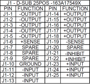
- CONTROL FEATURESON/OFF “INHIBIT” - Short inhibit lines together, or apply TTL LOW from +INHIBIT to -INHIBIT.
- WEIGHT2.0lbs max
- ENVIRONMENTAL CONDITIONSMIL-STD-810
Shock: Method 516.6, Procedure IV
Vibration: Method 514.5
Humidity: Method 507 (Converter operates without any evidence of degraded performance in non-condensing relative humidity up to 95%. All assemblies conformal coated).
Altitude: Method 500.4, Procedure I & II
Salt Fog: Method 509.4
High Temperature: Method 501.4, Procedure I & II
Low Temperature: Method 502.4, Procedure I
Sand and Dust: Method 510.4, Procedure I & II
Explosive Atmosphere: Method 511.4, Procedure
Acceleration: Method 513.5, Procedure I & II - CONNECTOR (J1)DB25 163A17549X, MATE: 164X11789X
- MATERIALAluminum 6061-T6 or eq
- FINISH (BASEPLATE)Chemical Film MIL-DTL-5541, Type II, Class 3 (Clear)
- FINISH (COVER)Anodize MIL-PRF-8625 Type 2 Class 2 (Black)
Fast, Stable Power for Mission Critical Loads
Low droop + fast recovery during high dI/dt load steps helps keep downstream electronics in regulation (reset immunity, tighter voltage margin).
Ideal for loads with large, fast current steps, such as Pulsed RF front ends (radar/EW, active antennas, T/R modules), software-defined radios, mission/AI compute nodes (CPU/FPGA/GPU), networked communications, and sensor processing where transient stability drives filtering size, architecture complexity, and qualification risk.
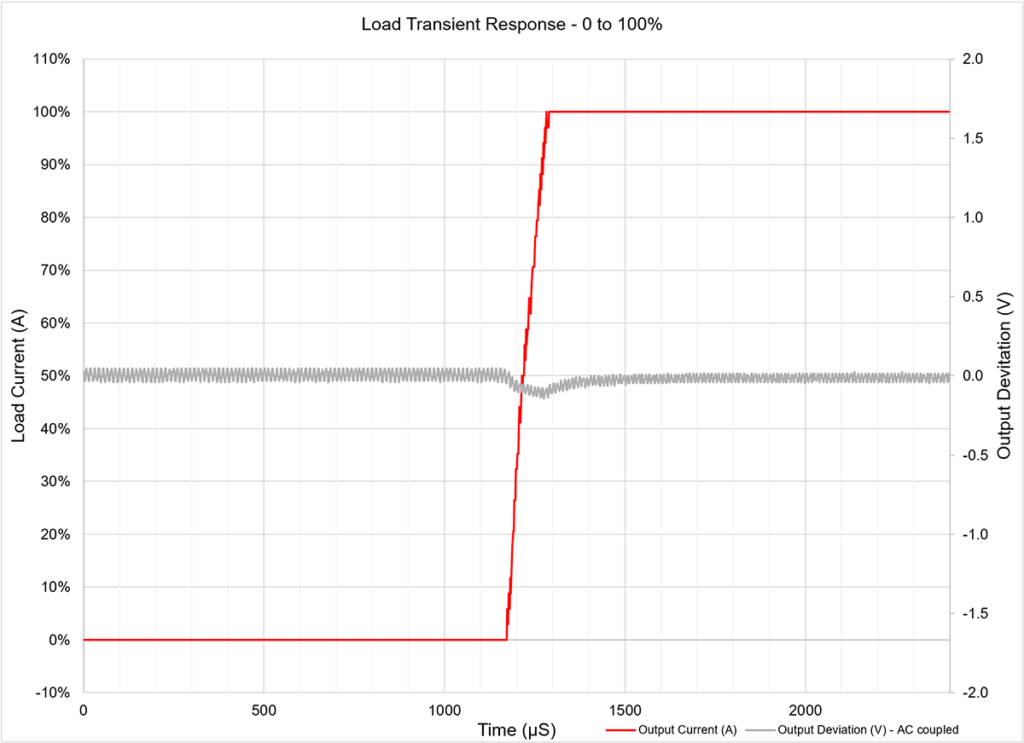
LOAD TRANSIENT RESPONSE, NL-FL:
INPUT: 28VDC
OUTPUT: 15VDC @ 13.3A, RESISTIVE LOAD
LOAD TRANSIENT DEVIATION OF 100mV (0.66%)
100μS RECOVERY TIME
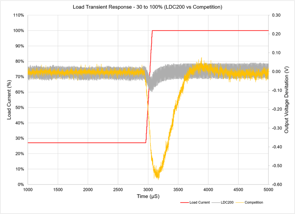
LOAD TRANSIENT RESPONSE COMPARISON WITH TYPICAL DC-DC CONVERTER:
INPUT: 28VDC
OUTPUT: 20VDC @ 10.0A, RESISTIVE LOAD
OUTPUT VOLTAGE DEVIATION:
LDC200: 70mV (0.35%), COMPETITION: 580mV (2.80%)
OUTPUT VOLTAGE RECOVERY TIME:
LDC200: 100μS, COMPETITION: 1300μS
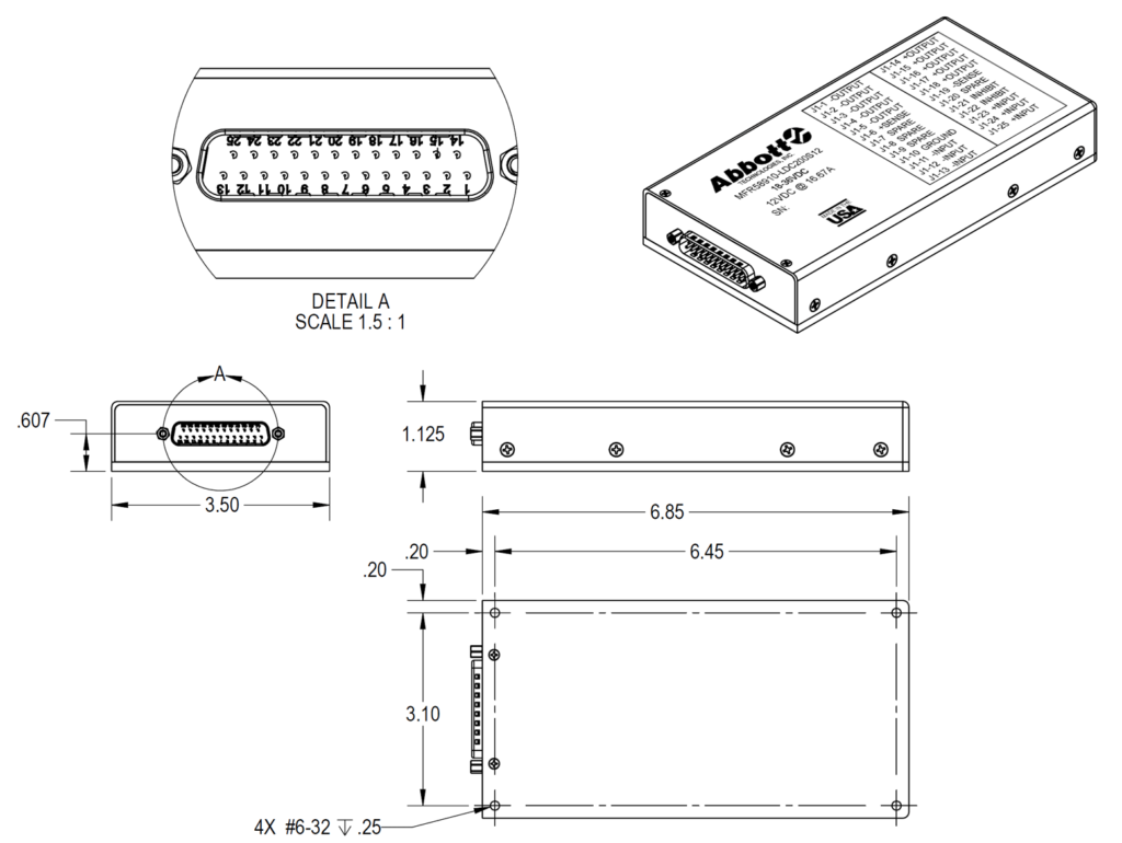
Mechanical Drawings
Available Model Listing
| Model Number | OUTPUT VOLTAGE | OUTPUT CURRENT | LINE REGULATION | LOAD REGULATION | RIPPLE AND NOISE (PARD) | LOAD TRANSIENT RESPONSE (NL-FL) | TURN ON OVERSHOOT | EFFICIENCY (FULL LOAD) | OUTPUT POWER | RFQ |
|---|---|---|---|---|---|---|---|---|---|---|
| LDC200S3.3 | 3.3VDC | 16.67A | ±0.1% | ±0.3% | ±2.0% | <2.0%,100μS | <0.2% | 75% MIN | 55W | RFQ |
| LDC200S5 | 5.0VDC | 16.67A | ±0.1% | ±0.2% | ±1.0% | <2.0%,100μS | <0.2% | 80% MIN | 83W | RFQ |
| LDC200S12 | 12VDC | 16.67A | ±0.1% | ±0.1% | ±0.5% | <2.0%,100μS | <0.2% | 88% MIN | 200W | RFQ |
| LDC200S13.6 | 13.6VDC | 14.71A | ±0.1% | ±0.1% | ±0.5% | <1.0%,100μS | <0.2% | 88% MIN | 200W | RFQ |
| LDC200S15 | 15VDC | 13.33A | ±0.1% | ±0.1% | ±0.5% | <1.0%,100μS | <0.2% | 89% MIN | 200W | RFQ |
| LDC200S24 | 24VDC | 8.33A | ±0.1% | ±0.1% | ±0.3% | <0.5%,100μS | <0.2% | 90% MIN | 200W | RFQ |
| LDC200S28 | 28VDC | 7.14A | ±0.1% | ±0.1% | ±0.3% | <0.5%,100μS | <0.2% | 91% MIN (93% TYP) | 200W | RFQ |