
MIL-STD-1275 Power Supplies
Selecting DC-DC converters and input conditioning for 28 Vdc military ground vehicle power
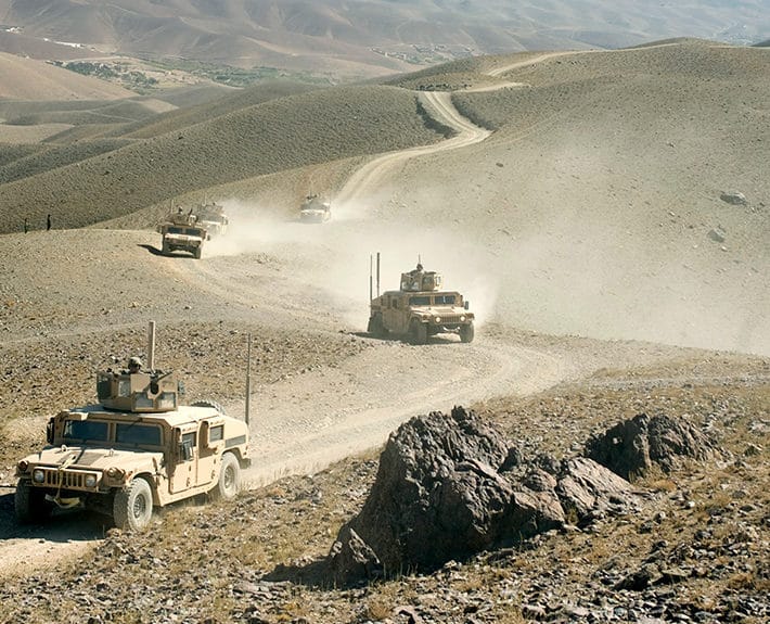
The 28 Vdc bus on a military ground vehicle is one of the harshest DC power sources a piece of equipment will see. The engine start collapses the bus toward battery-cranking voltage, load changes and alternator behavior drive surges well above the nominal voltage, and the electrical system produces fast, high-voltage spikes. A converter that only regulates over a comfortable input range will not survive it.
MIL-STD-1275 defines the characteristics of 28 Vdc electrical power at the input terminals of utilization equipment installed in military vehicles. It is an interface standard: the vehicle power system produces disturbances within the defined envelope, and the connected equipment must operate through, survive, or recover from them as specified. It covers steady-state voltage, ripple, surges, spikes, and the starting and cranking disturbances that come with a vehicle electrical system.
MIL-STD-1275 is a DC ground-vehicle standard, distinct from the aircraft power in MIL-STD-704 and the shipboard power in MIL-STD-1399. Treating its transient envelope as an input-architecture requirement early, rather than a late qualification surprise, is what keeps the vehicle bus from destroying otherwise good electronics. This page explains what MIL-STD-1275 asks of a power supply and how Abbott can help you meet it.
What MIL-STD-1275 Asks of Your Power Supply
MIL-STD-1275 is not just a nominal voltage. It defines a set of disturbances the equipment must tolerate at its input terminals. For a DC-DC converter, that affects several design areas:
| Design area | Why it matters |
|---|---|
| Steady-state input range | The converter must regulate continuously across the full steady-state band, which is wider than the 28 Vdc nominal and includes ripple on the bus. |
| Voltage surges | Load changes and alternator behavior drive the bus well above nominal for hundreds of milliseconds. The input stage must clamp or ride through these surges without damage or shutdown. |
| Voltage spikes | Fast, high-voltage, energy-limited spikes appear on the bus. Input transient suppression has to absorb them before they reach the converter. |
| Starting and cranking | Engine start collapses the bus toward battery-cranking voltage for up to tens of seconds. Equipment that must keep operating needs holdup or wide undervoltage ride-through. |
| Ripple and conducted noise | Ripple limits reference MIL-STD-461 CS101, so the MIL-STD-1275 input behavior and the MIL-STD-461 EMI requirement have to be engineered together. |
| Reverse polarity and protection | Vehicle installation and jump-start conditions make reverse-polarity and overvoltage protection part of the input design, not an afterthought. |
| Evidence and configuration control | The configuration tested must match the configuration delivered. Input protection, filtering, and harnessing all affect the result and the evidence. |
The practical takeaway: on a vehicle bus, the input protection and holdup are as much a part of the specification as the output rails.
MIL-STD-1275 Disturbances (Quick Reference)
MIL-STD-1275 defines the 28 Vdc disturbances as voltage-time envelopes and waveforms, measured at the equipment input power terminals. The values below are from MIL-STD-1275E, the current revision (22 March 2013). Earlier revisions differ, so confirm the limits against the revision your program invokes.
| Condition | Limit (MIL-STD-1275E) | Notes |
|---|---|---|
| Nominal voltage | 28 Vdc | Vehicle system nominal |
| Steady-state operating range | 20 to 33 Vdc, including ripple | Continuous band; excludes engine starting |
| Ripple | Per MIL-STD-461 CS101 (the 150 kHz values extended to 250 kHz), verified at 23 and 30 Vdc | Ties the input requirement to the EMI requirement |
| Starting, initial engagement surge (IES) | Down to 12 Vdc, up to 1 second | Deepest, briefest crank dip; consecutive events at least 1 second apart |
| Starting, cranking | Down to 16 Vdc, up to 30 seconds | Equipment required to operate through must ride this out |
| Voltage spikes, immunity | ±250 V peak at 70 µs, returning to the envelope by 1 ms; rise time up to 50 ns; injected energy up to 2 J | Equipment must operate without degradation or damage |
| Voltage spikes, emissions | Emitted spikes limited to 125 mJ | Limit on what the unit may put back on the bus |
| Positive surge (alternator load dump) | +100 V peak for about 50 ms, recovering to the 20 to 33 V band within about 500 to 600 ms; injected energy up to 60 J | Sudden loss of a high or inductive load |
| Negative surge | Down to 18 Vdc for about 500 ms | Sudden application of a high-demand load |
Selection note: MIL-STD-1275 disturbances are envelopes and waveforms, not single min and max numbers, and the values differ across revisions (for example 1275B, 1275D, and 1275E). The standard defines the power at the equipment input terminals and covers voltage only; it explicitly leaves electromagnetic interference and electrostatic discharge to the applicable performance specification. Confirm the invoked revision and the specific waveforms before you fix the input design.
Why input conditioning, not just a converter: a DC-DC converter with an 18 to 36 Vdc input range regulates fine at nominal voltage, but on its own it will not survive the ±250 V spikes or the +100 V surges, and it will drop out during a 12 V cranking dip. Full MIL-STD-1275 compliance requires designed-in input transient suppression, surge clamping, reverse-polarity protection, and enough holdup or undervoltage ride-through to keep operating through engine start. That input stage is the hard part of a MIL-STD-1275 design, and it is exactly where a fixed catalog module falls short and a purpose-built or adapted design earns its place.
Abbott Power for 28 Vdc Ground Vehicle Applications
Abbott does not currently offer a standard catalog product qualified to the full MIL-STD-1275 envelope. There are two paths, depending on how much of the disturbance envelope your program actually invokes:
| Option | Power | Input | What it covers | Best for | |
|---|---|---|---|---|---|
 |
LDC200 and other 18-36 Vdc DC-DC converters | 200 W | 18-36 Vdc | The MIL-STD-1275 nominal steady-state band. Customers have used these in ground applications where the input stays within the 18 to 36 Vdc range and the full MIL-STD-1275 surge, spike, and cranking envelope is not invoked. | Ground vehicle and vetronics electronics on a controlled or pre-conditioned 28 Vdc bus; sub-1275 applications |
| — | Custom and modified MIL-STD-1275-compliant designs | Application-specific | 28 Vdc vehicle bus | The full MIL-STD-1275 envelope: surge, spike, reverse-polarity, and cranking ride-through, built into the input stage. | Programs that invoke complete MIL-STD-1275 compliance, including obsolete vehicle-power replacement |
On standard products and full compliance: Abbott’s design library includes MIL-STD-1275-compliant power converters, but they are not currently offered as published standard catalog products. Full-1275 requirements are met by building or adapting a design to your specification. If your requirement stays inside the 18 to 36 Vdc range without the full transient envelope, the LDC200 may fit as a standard product. If it invokes the complete MIL-STD-1275 surge, spike, and cranking envelope, send us the requirement and we will scope a compliant unit from the library.
Getting the Selection Right
The hard part of MIL-STD-1275 is rarely the nominal voltage. It is the transient envelope and the cranking behavior, and being honest about which of them your application really invokes.
- Separate “operates on 28 Vdc” from “MIL-STD-1275 compliant.” A converter that regulates over 18 to 36 Vdc covers the nominal bus, but that is not the same as surviving the full surge, spike, and cranking envelope. Decide which one your program requires before you select.
- Let the transient envelope drive the input stage. The surges, spikes, and reverse-polarity conditions set the input protection design. Size that first, not the regulator.
- Decide operate-through versus survive for cranking. If the equipment must keep running during engine start, you need holdup or wide undervoltage ride-through down to the cranking voltage, not just survival.
- Engineer the MIL-STD-1275 input and the MIL-STD-461 EMI together. Ripple limits reference 461 CS101, so the input filter and protection serve both requirements. See our MIL-STD-461 guide.
- Confirm the revision. The values and waveforms differ across MIL-STD-1275 revisions. Match the design to the revision the program invokes.
- Use a proven design as the baseline. Adapting an existing MIL-STD-1275-compliant design to your outputs and package is lower risk than starting from a blank sheet, and it is how most vehicle-power requirements are best served.
Selection Checklist
Define these items before you commit to a power supply for a MIL-STD-1275 application:
| Requirement | What to define |
|---|---|
| Invoked standard | MIL-STD-1275 revision, any program-specific tailoring, and the equipment detail specification. |
| Compliance level | Whether the application needs full MIL-STD-1275 immunity or only operation within the 18 to 36 Vdc steady-state band. |
| Steady-state range | The continuous input band and ripple the converter must regulate across. |
| Surge and spike | The surge peak and duration and the spike waveform and energy the input must clamp or ride through. |
| Cranking behavior | Operate-through or survive during initial engagement and cranking, and the minimum voltage and duration. |
| Protection | Reverse polarity, overvoltage, jump-start, and fault behavior required by the installation. |
| Output rails | Voltage, current, regulation, ripple and noise, sequencing, isolation, and load-step behavior. |
| EMI strategy | MIL-STD-461 requirements, especially CS101 ripple, input filtering, and grounding. |
| Thermal path | Baseplate, chassis, forced air, cold plate, enclosure rise, and derating for the vehicle thermal environment. |
| Mechanical environment | Shock, vibration, ingress, and mounting for the vehicle platform, commonly per MIL-STD-810. |
| Evidence package | Datasheet, analysis, similarity, or qualification and acceptance testing required by the program. |
| Lifecycle support | Configuration control, obsolescence planning, and replacement strategy for long vehicle-program lifecycles. |
Integrating the Supply
A MIL-STD-1275-capable power supply still needs a disciplined installation. Treat the power entry as an integrated subsystem:
- Place input transient protection and filtering at the power entry, close to the vehicle bus connection.
- Keep input power, output power, and low-level control or sense wiring separated where practical.
- Use the vehicle grounding and bonding approach; do not rely on the chassis as a power return unless the platform architecture allows it.
- Confirm reverse-polarity and jump-start protection are consistent with the vehicle maintenance practice.
- Verify thermal performance at worst-case ambient, mounting orientation, load, and cooling condition for the vehicle environment.
- Match the delivered input protection and harnessing to the configuration used in qualification.
The goal is to make the qualification configuration look like the installed configuration.
How Abbott Supports Your MIL-STD-1275 Requirement
Abbott builds power conversion hardware for programs where electrical survivability, environmental ruggedness, configuration control, and lifecycle support all matter. For 28 Vdc ground vehicle power, our 18 to 36 Vdc DC-DC converters serve applications that stay within the nominal steady-state band, and our design library includes MIL-STD-1275-compliant converters that we build or adapt to the full disturbance envelope when a program requires it.
Because we design our own power electronics and maintain a large library of custom and modified power supply designs, we can start from a proven MIL-STD-1275-compliant baseline and tailor the outputs, packaging, and protection to your vehicle application, which lowers both risk and schedule compared with a clean-sheet design. This same in-house capability makes Abbott a practical source for replacing obsolete or unsupported vehicle power supplies form, fit, and function. We maintain full configuration control and support customers from consultation and prototyping through production and legacy sustainment. Abbott is AS9100 and ISO 9001 certified, and does not obsolete products without full consideration.
Send us the invoked MIL-STD-1275 revision, whether you need full compliance or operation within the 18 to 36 Vdc band, the output rails, cranking and holdup requirements, thermal and mechanical constraints, and required evidence package. Our application engineers will tell you whether a standard converter fits or a compliant design from the library is the right answer. Contact us or complete the power supply design form.